
Gust Delegate: Building an Electric Moped (E-Bike)
Originally written in Polish and translated into English.
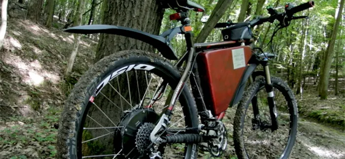
The idea of building an e-bike came about as early as 2011. The assumptions were as follows: a 250 W motor, 48 V so that the power could be raised to 500 W, a hub motor in the front wheel, gel batteries, and a capacity for about 150 km of range. The project slowed down after the idea and some research into components. At the beginning of 2015 I returned to it. As it turned out, the market had changed enormously, and a whole range of motors, batteries, battery management systems and so on was now available. What I ended up building differs considerably from the initial assumptions. It is a bike with high-end components, converted to electric drive based on the ebike.nexun.pl build tutorial. The project cost a lot of time, money and health, but it was WORTH it!!!
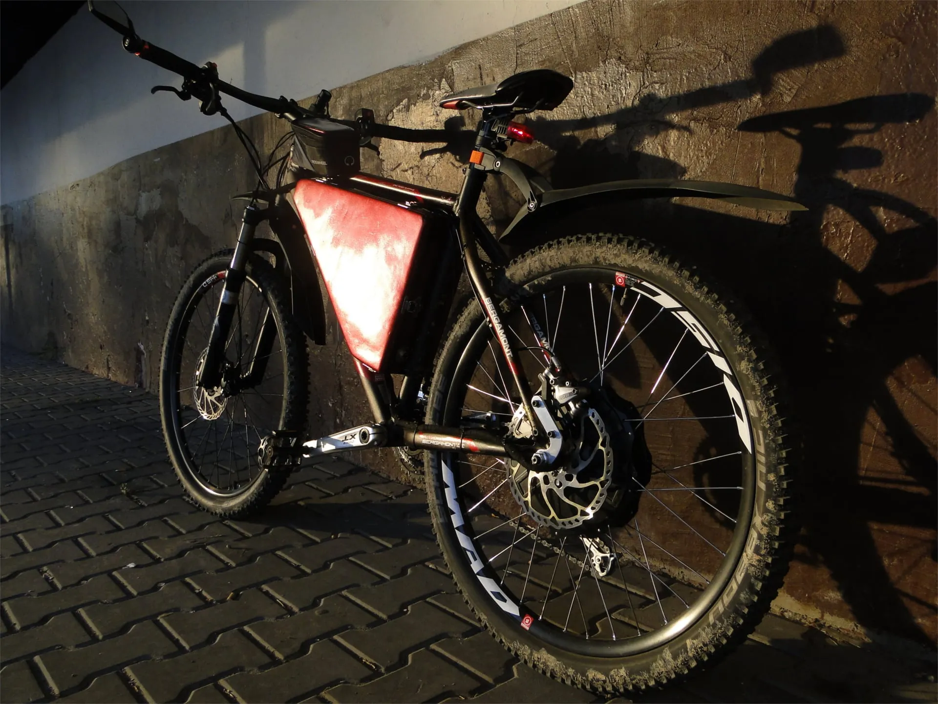
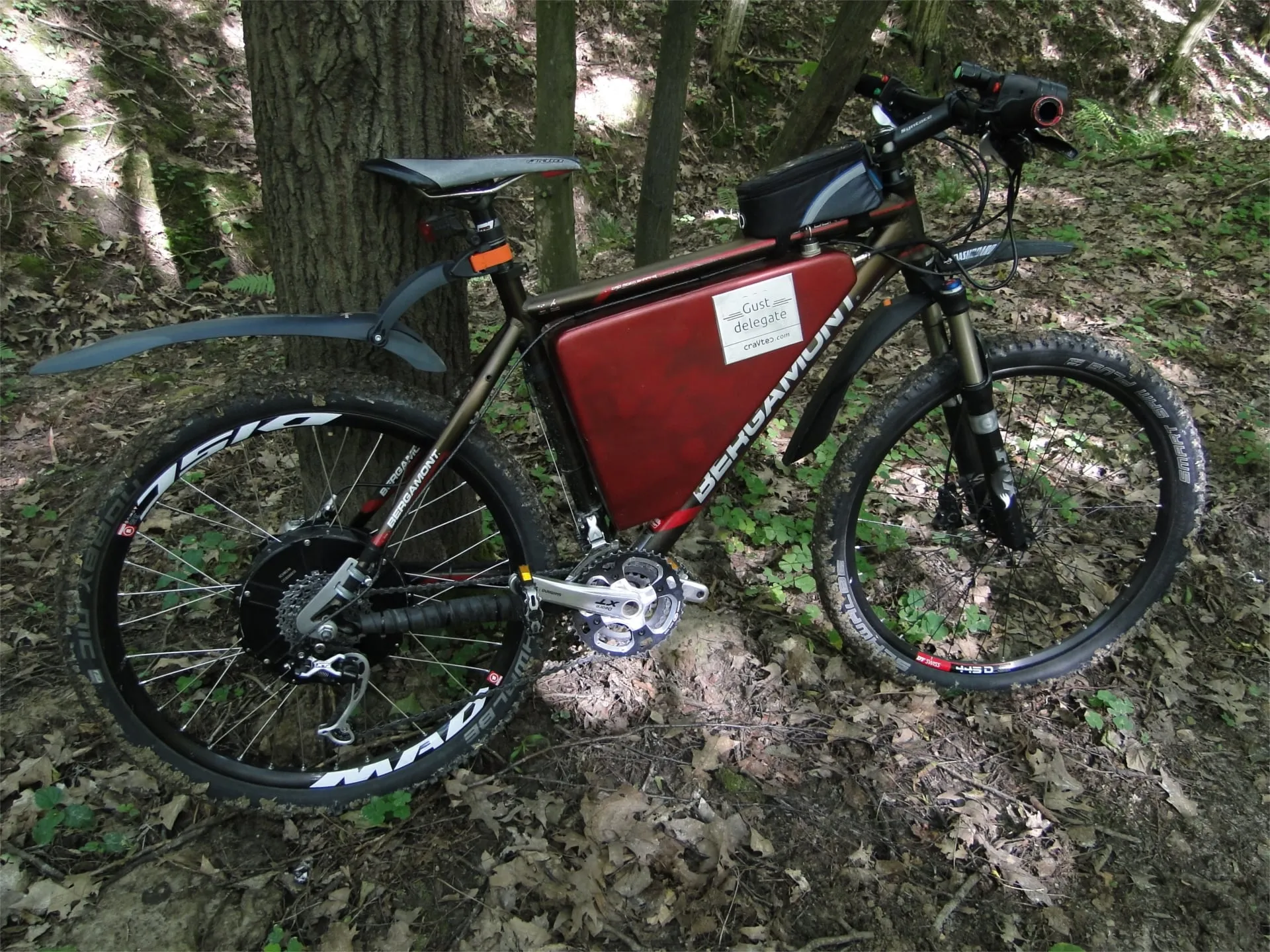
Below are the parts list and a short specification, in tables.
Frame and steering
| Part | Model |
|---|---|
| Frame | Bergamont Platoon 8.0 |
| Headset | Syntace Duraflite |
| Seatpost | Tattoo pro |
| Handlebar | Ritchey comp 720 mm |
| Stem | SYNTACE - Force MTB F148 |
Front wheel
| Part | Model |
|---|---|
| Front rim | DT Swiss X-445, 32 spokes |
| Front hub | Shimano XT |
| Front spokes | 1.5 mm |
| Front tyre | Schwalbe Smart Sam Plus 26’‘x2.35’’ |
| Front rotor | 185 mm Shimano XT |
| Front caliper | Shimano XT hydraulic |
| Front fork | Fox O/B RL 32 mm F1000, 2010 |
Rear wheel
| Part | Model |
|---|---|
| Rear rim | Mach1 Mad Disc, 36 spokes, 26’’ |
| Rear hub | Nine Continents 10x6, cassette version |
| Rear spokes | 2 mm |
| Rear tyre | Schwalbe Nobby Nic 26’‘x2.25’’ |
| Rear rotor | Shimano SLX 180 mm |
| Rear caliper | Avid Elixir R Carbon |
| Rear suspension | None :( |
Components
| Part | Model |
|---|---|
| Cassette | SRAM PG-980, 11-32, 9-speed |
| Crankset | SHIMANO Deore XT, 44/32/22 |
| Rear and front derailleur | Shimano XT |
| Rear and front shifter | Shimano XT |
| Pedals | Dartmoor machined platform pedals |
| Grips | Vincere, hex-bolt clamp |
| Mudguards | SKS Dashboard and X-Blade |
| Saddle | Selle Royale Look In Moderate |
Electrics and electronics
| Part | Model |
|---|---|
| Batteries | Turnigy 4s 10Ah LiPo |
| Battery configuration | 16s2p |
| BMS | 60 A, 16s |
| Motor controller | 40 A barmal controller from the arbiter forum |
| Motor | Nine Continents 10x6 |
| Throttle | Chinese, 1 latching switch + battery level indicator |
| Buttons | Chinese, 1 momentary and 1 latching |
| Charger | 8 A LiPo/LiIon |
| Box | Epidian resin and fibreglass mat |
Specification
| Parameter | Value |
|---|---|
| Weight | Exactly 30 kg |
| Height to the top of the stem | 102 cm |
| Length | 175 cm |
| Width | 74 cm |
| Maximum speed | 70 km/h unloaded |
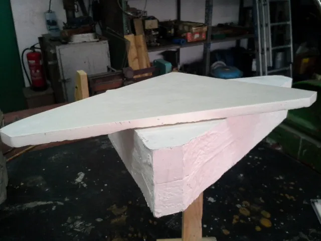
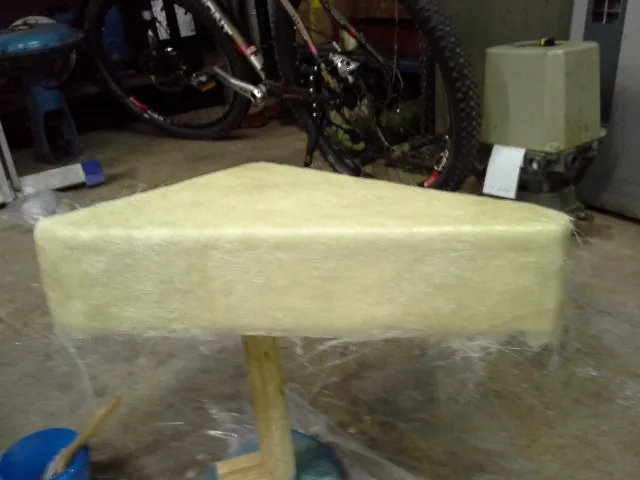
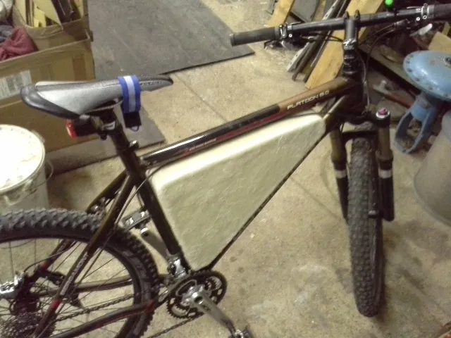
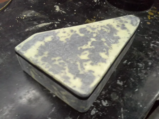
As I wrote earlier, the e-bike is built on solutions found on ebike.nexun.pl and forum.arbiter.pl (a Polish electronics forum). The electronics box was first carved from Styrodur foam, in two parts: the lid and the main body. Both parts were covered with filler and then coated with polyvinyl alcohol (PVA) release agent to make them easier to separate from the mould. Next they were covered with three layers of fibreglass mat soaked in Epidian resin. Finally, the box was sanded and levelled with car body filler. I had planned to have it sprayed with filler primer and painted professionally, but the box came out a bit uneven, so I treated it as a prototype and painted it with ordinary red metallic spray paint.
The BLDC motor is driven by a FOC controller from the user barmal on forum.arbiter.pl. It is attached to the box through the heatsink shown below. The resin box is a very good insulator and it can get really warm inside, which is why I chose this solution. The heatsink is fastened with six threaded M5 studs. Around the heatsink, on the inside, there is room for a gasket. The FOC controller enclosure is attached to four pads with threaded M5 holes.
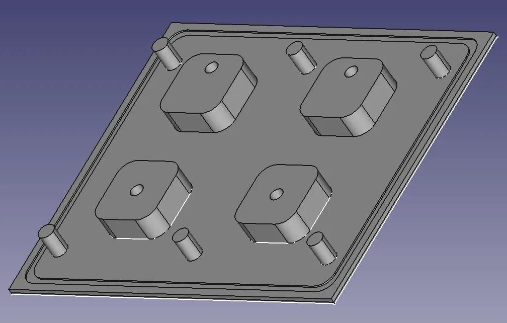
Below is the outer side of the heatsink, which dissipates heat from the box. It has no fins because this is where the knee reaches, and I did not want it to stick out too far and rub against the inside of the leg.
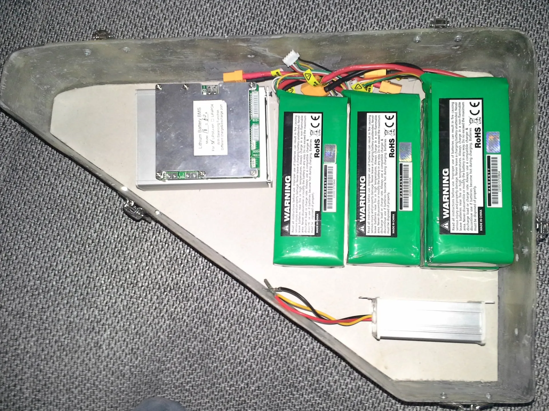
The layout of the components in the box is shown in the picture below. The batteries have a separate compartment made of 1.5 mm aluminium sheet. The BMS is mounted above the FOC controller, and a 12 V inverter sits under the LiPo pack. In the upper left part there is also an ignition switch (not visible in the photo).
Below is the wiring diagram of the resin box. The battery pack is connected to the BMS, which manages the cells and balances their voltages. The BMS disconnects the ground to switch the batteries between charging and discharging mode. A 40 A DC circuit breaker is installed on the battery positive. The positive voltage to the FOC controller is switched by two parallel NO contacts of automotive relays. These contacts are closed by the ignition switch, which starts the 12 V inverter and supplies that voltage to the relay coils. Twelve wires come out of the motor: three phase wires, five for the Hall sensors, two from the thermal fuse and the last two from the NTC thermistor temperature sensor. The FOC controller has four inputs, one for the throttle and three for the buttons EN, BR and DIR. DIR reverses the direction of rotation, while BR is used to switch off the cruise control and/or to apply regenerative braking. The EN (enable) input is a signal telling the controller whether it may start. In my build it is connected to the button on the throttle, in series with the thermal fuse and the NO contact of the ignition switch. For the controller to power the motor, the following conditions must be met: the motor must not be overheated, the ignition must be on, and the button on the throttle must be pressed.
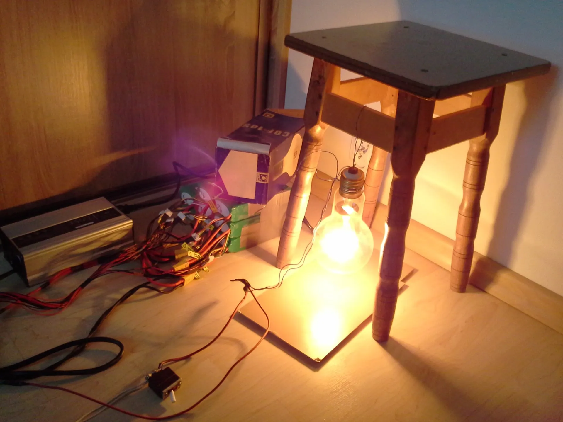
The most expensive part of the bike is the batteries. Unfortunately, they will have to be replaced every few years, which will hit my wallet again. As I learned later, I bought one of the worse brands, and I have heard many negative opinions about them. But as they say, we’ll see. Below is a picture from the first charge and discharge tests of the 16s2p pack.
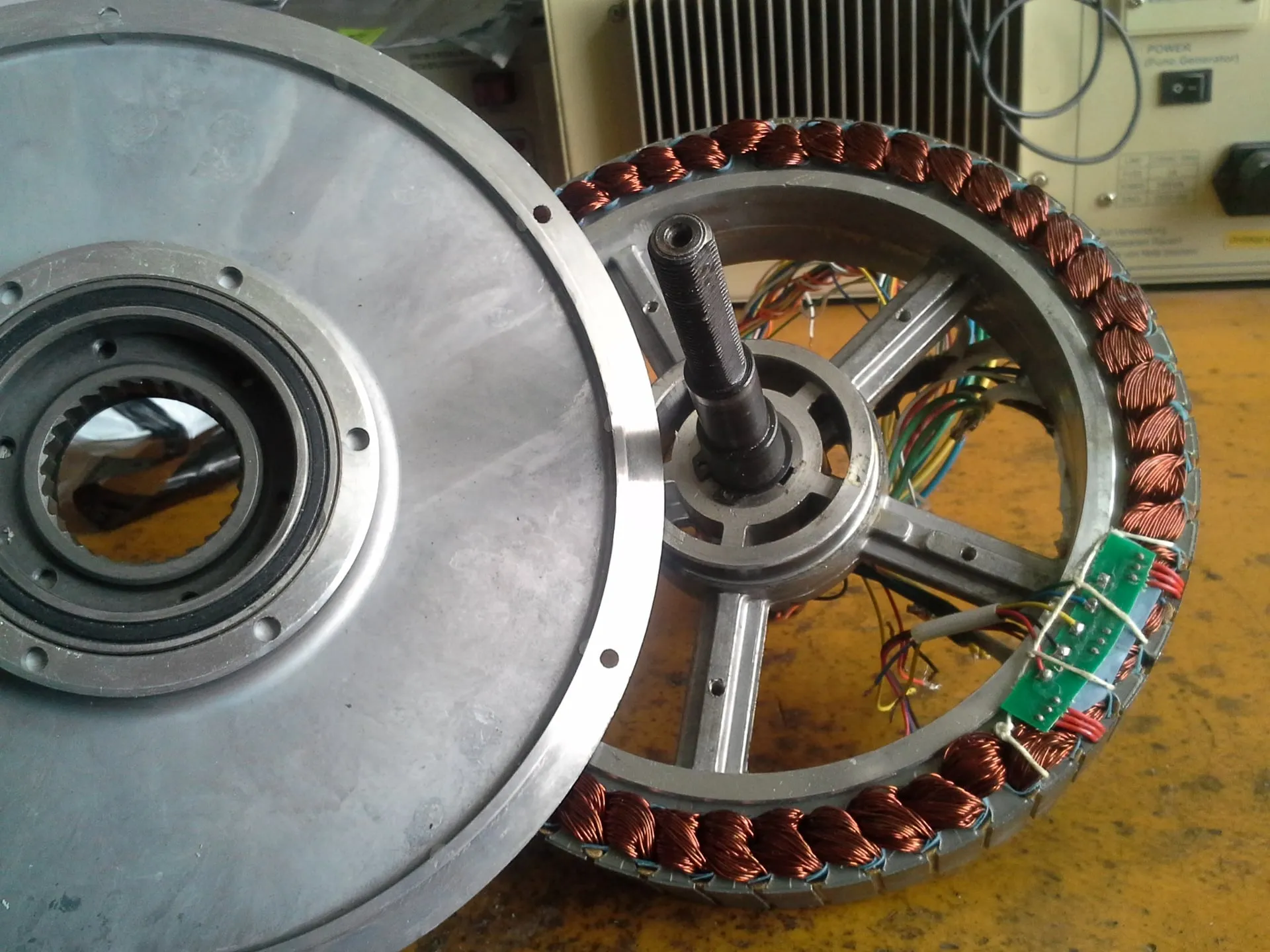
It turned out that the dropouts in the bicycle frame cannot withstand the motor torque, and the motor axle slides out of them. After the first test ride, the motor fell out of the frame. Fortunately, nothing serious happened. The signal wires were torn off and a Hall sensor in the motor burned out. The damage was repaired after a few weeks.
What remained was to make torque arms that hold the axle in place. The design was made in DXF format and milled on a CNC milling machine. The first arm was bolted with M6 screws to the brake caliper mount, while the second was attached to the frame with metal clamps.
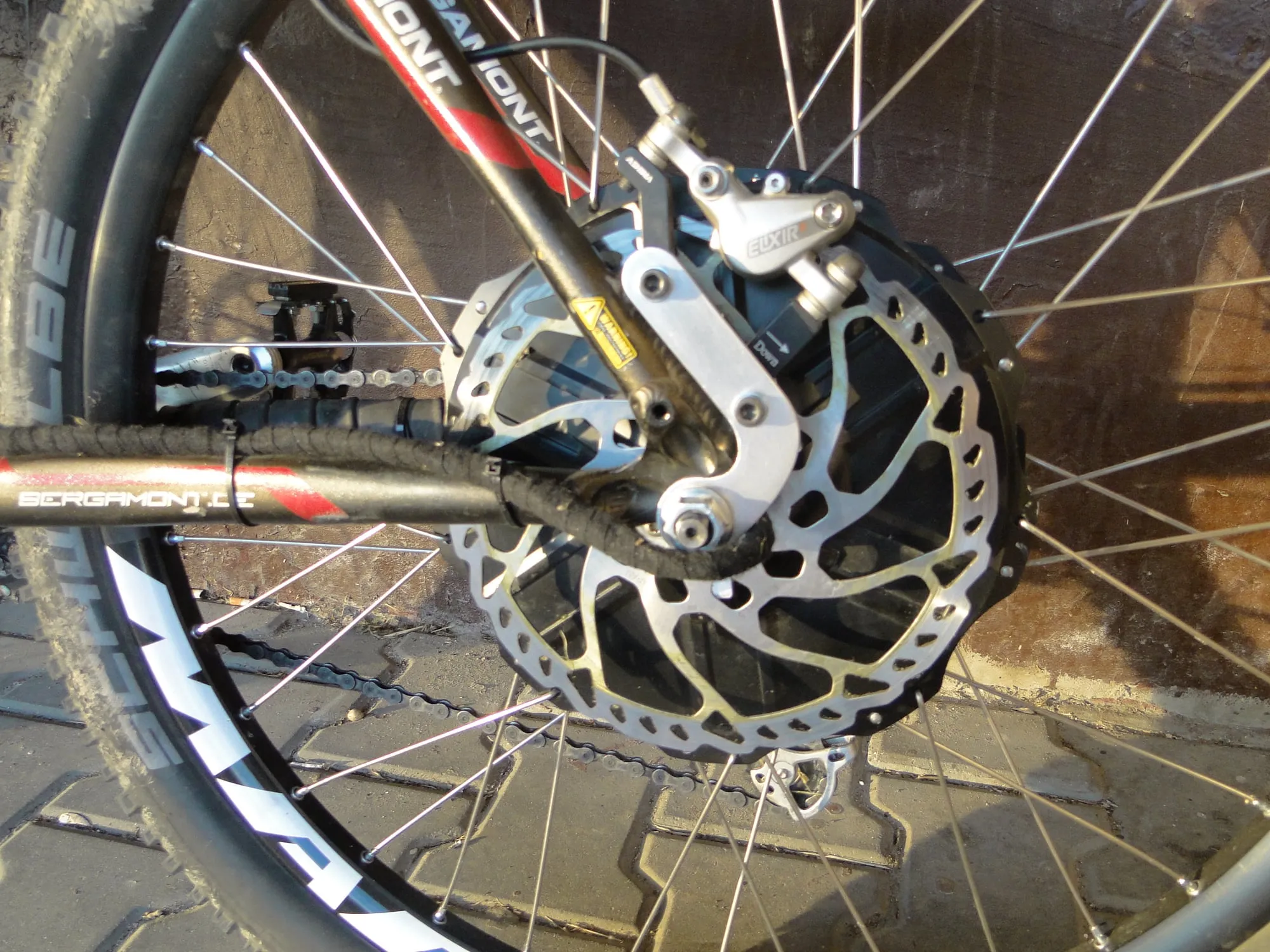
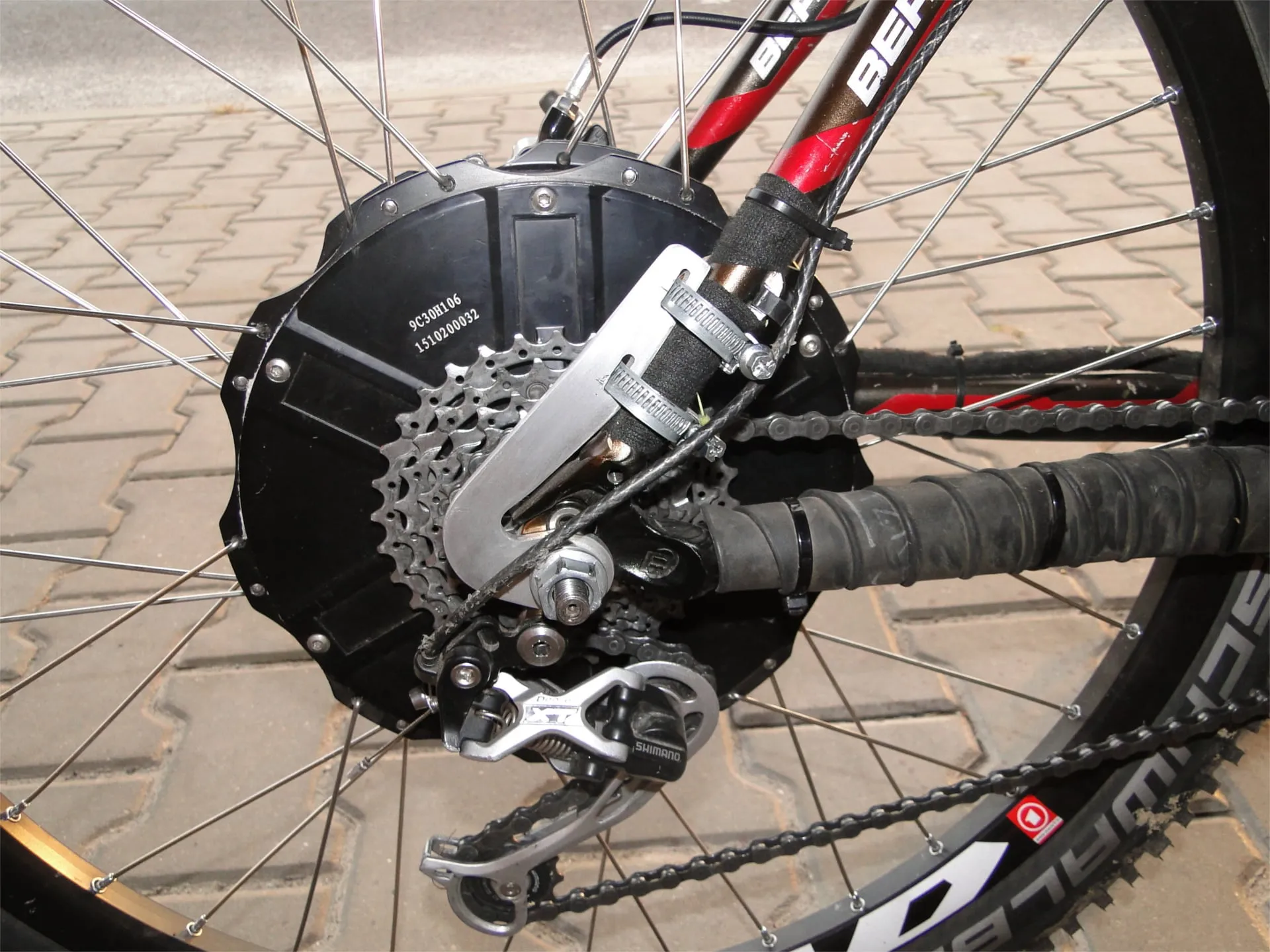
Here is a photo of the e-bike still on the old rim and without the arms holding the axle. Unfortunately, the rim could not take the load and the spokes were too thin. It was replaced with a Mach1 Mad rim with 2 mm spokes.
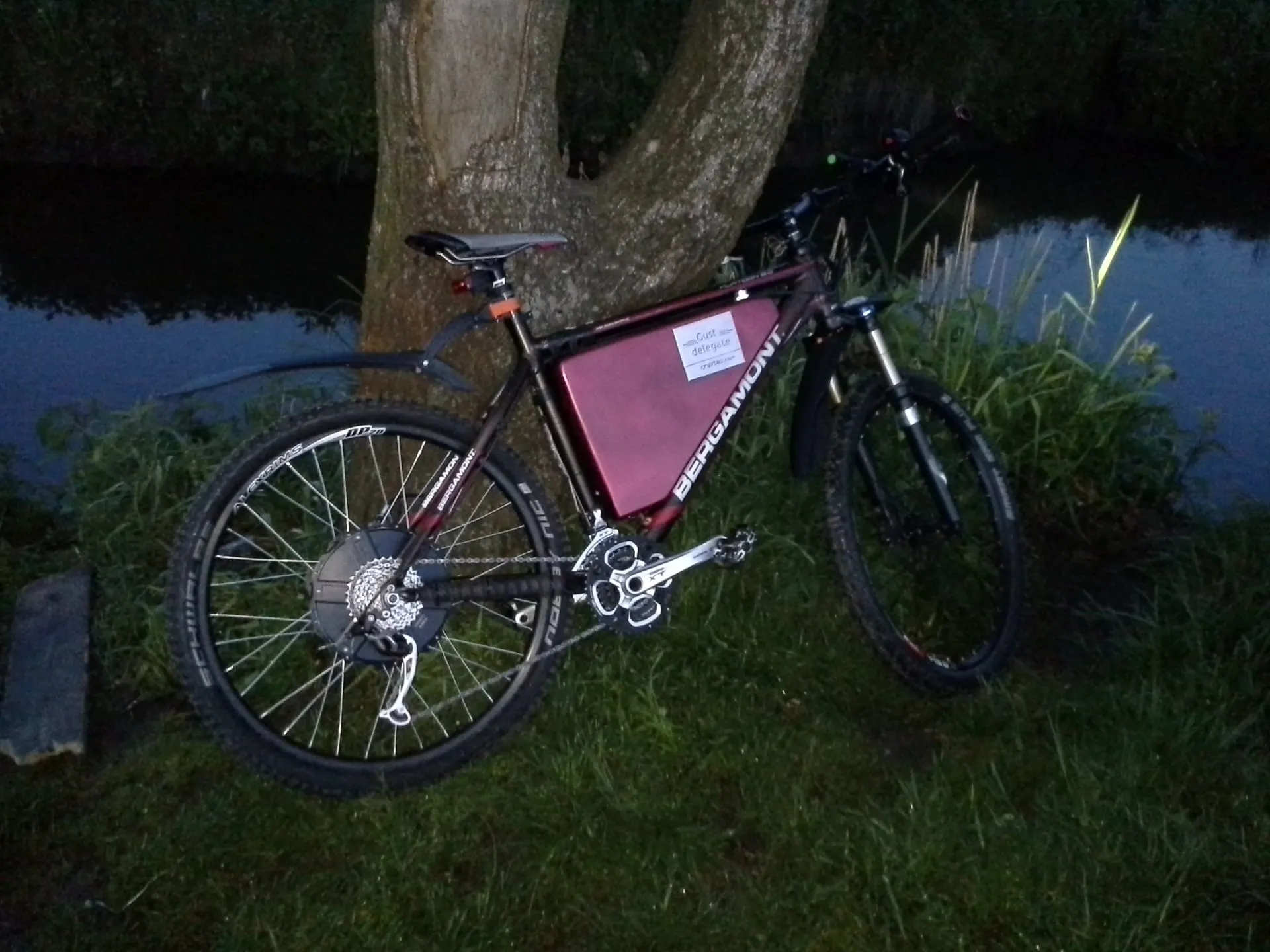
Drawbacks and things to change:
The saddle is a terrible plank. After 110 km I got blisters, I won’t say where.The pedals must be changed to platform ones.- The lack of rear suspension hurts. Literally.
- The lack of a chainring guard is also a bit annoying.
And the biggest drawback is the rear brake. The rotor is probably too large, the caliper keeps rubbing against it, and braking produces a loud squeal. I plan to change the rotor to a 185 mm one, if the caliper fits next to the motor.- And that ugly rear mudguard and the cheap mirror.
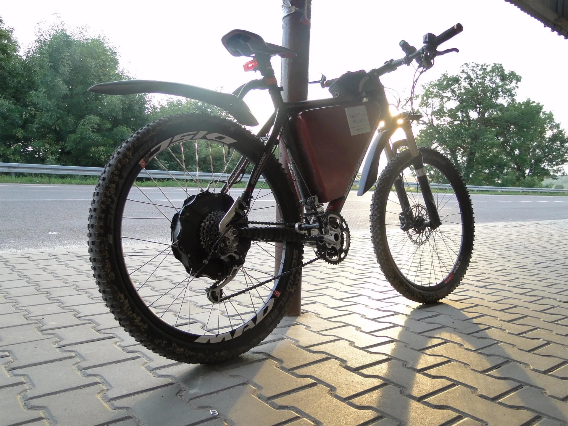
And finally, one more photo.
And a video of a ride: