
Which CAD/CAM Software for a Hobby CNC Mill? Free vs Paid
Originally written in Polish and translated into English.
Contents
Even before building or buying a CNC machine of our own, we face the dilemma of choosing software for modelling and for generating the code the mill will understand. For home use and small companies, free programs are the safest choice. But are they better than paid ones? In this article we describe the pros and cons of all the programs we have used. You will also find a description of the operations performed on CNC machines and a short summary of the basic commands of the G-code programming language.
1. CNC operations
Before choosing a milling program, we need to decide which operations we will perform. Below is a list of the basic ones; we will not need all of them. It depends on what we want to focus on: metal parts, or perhaps artistic woodwork?
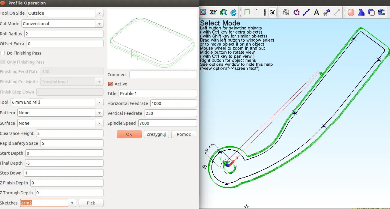
- Profile operation – a simple cut along a contour. It is also useful for chamfering, i.e. trimming sharp edges. In the illustration below the profile cut is marked in green. You can also see the step-downs along the Z axis, which are very useful when machining hard materials. After all, we do not want to plunge the whole cutter into a steel blank at once. A useful feature when generating toolpaths is so-called tabs (bridges). Their job is to hold the part in place during machining so that it does not move, especially during the last passes. In the figure below the tabs are marked with blue triangles.
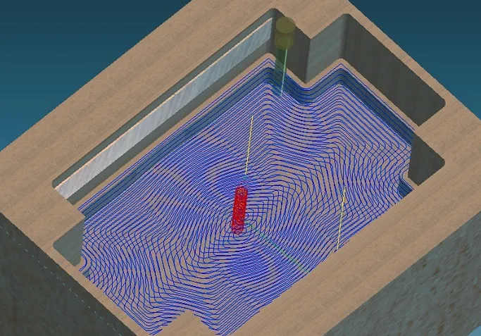
- Pocket – milling a hole or a recess. Here we should have the option of milling along the edge (as in the picture below) and plunging in the Z axis by a set increment. Simple programs generate code only as vertical passes, horizontal passes or a zigzag. As a result the part is not perfectly smooth and the edges look visibly ragged. So-called planar milling (facing) works on a similar principle: creating a flat surface for further machining. The difference is that here we make a pocket over the whole surface, with the same number of passes, which gives us a flat surface.
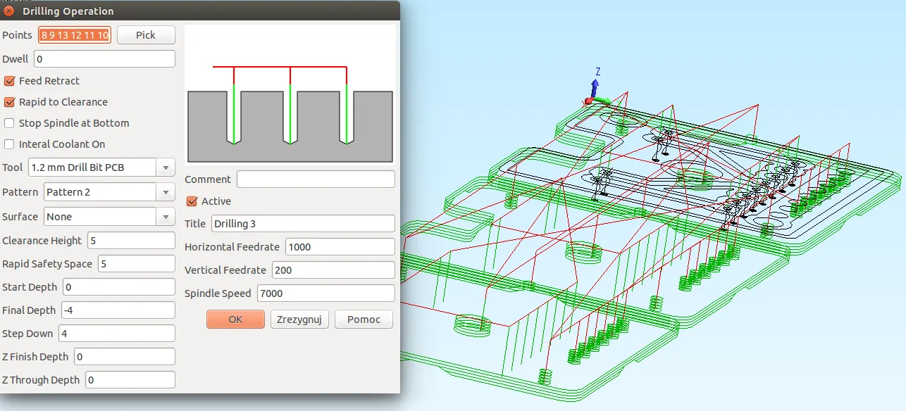
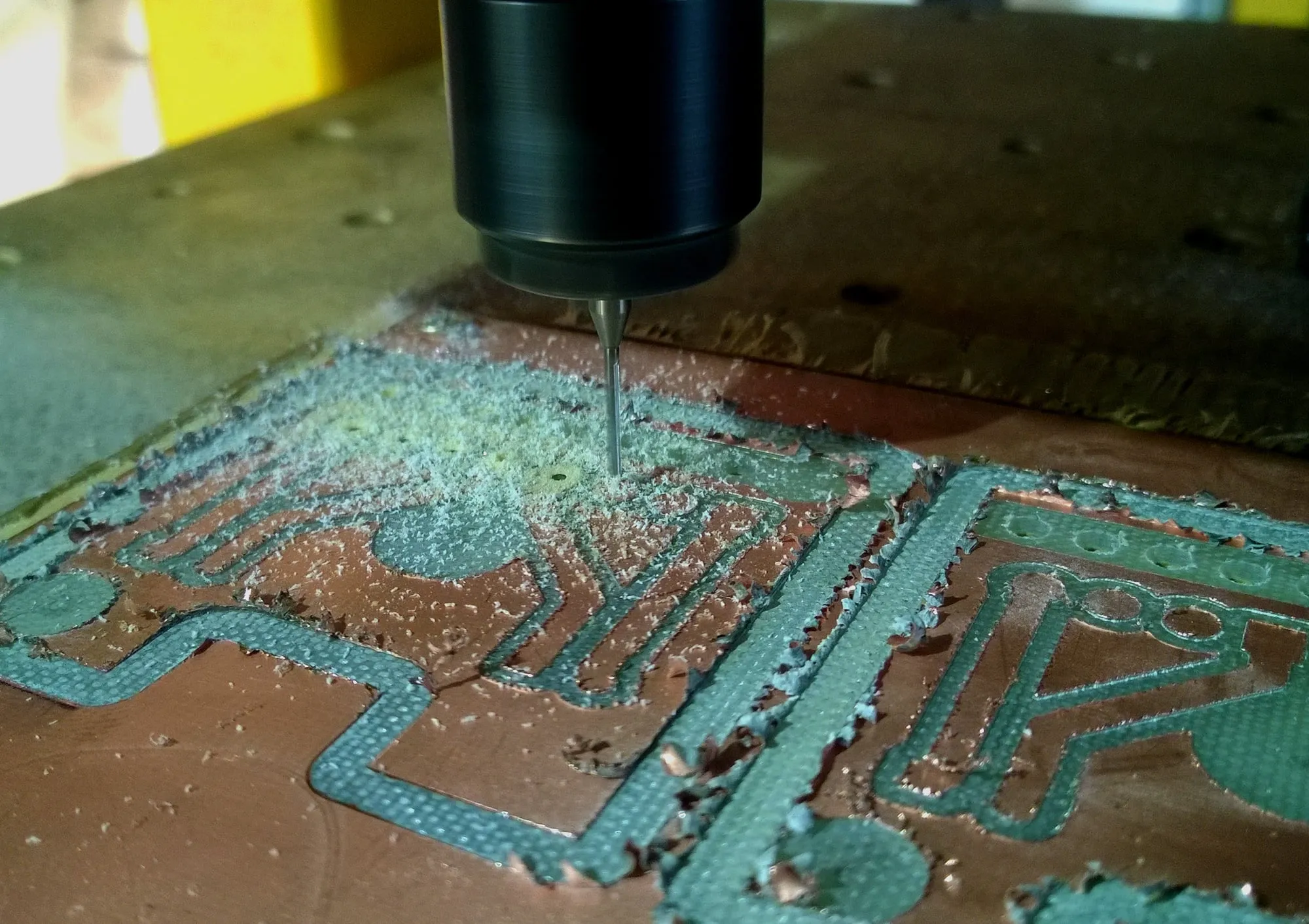
- Drilling – needs no commentary. Useful options here are chip breaking, periodic retraction to clear the material, and a dwell for a precise hole. Special types of drill bits are used for drilling on CNC machines.
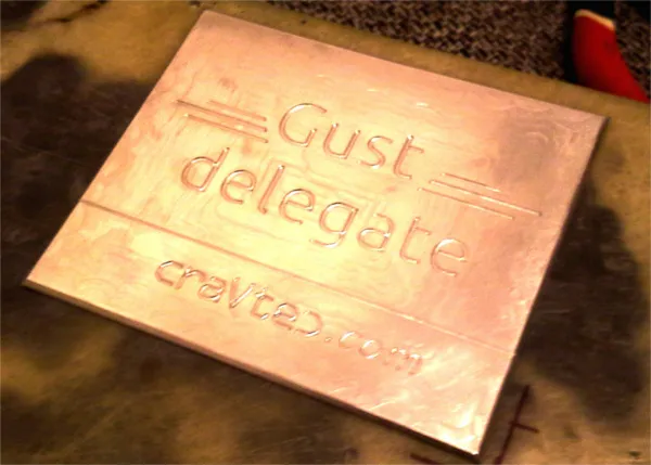
- Engraving – milling a groove, most often with a V-bit. In most CAM programs the cutter goes deeper or shallower into the material depending on the width of the path. For wide paths a pocket remains in the middle, which is usually milled with an end mill to get a flat surface. The photo below shows a faced aluminium plate with chamfered edges and engraving.
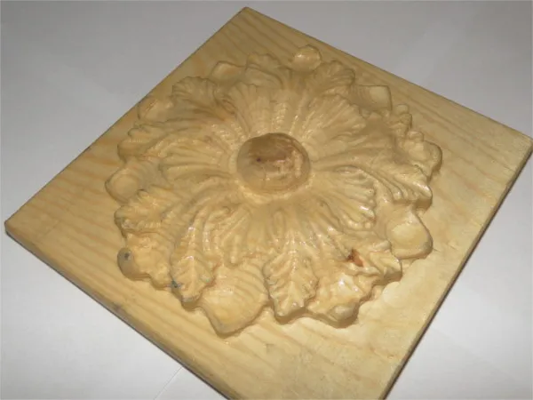
- 3D milling is cutting objects in full three dimensions. It helps to have two types of machining available: roughing and finishing. Roughing consists of passes in the X and/or Y axes with a flat end mill. The idea is to remove large layers of material as quickly as possible and prepare the stock for finishing with a small ball-nose cutter. This cutter runs right along the edge of the 3D object, smoothing it.
- Turning (mill-turning) – an option available for CNC lathes or machines with at least four axes, including a rotary axis. This is called mill-turning. The workpiece is rotated about its axis while the cutter makes a perpendicular, parallel or sometimes compound movement relative to the rotary axis. We have not used this operation yet, so we have no experience creating such programs.
2. Writing G-code by hand
If we own a CNC machine, it is worth knowing at least the basics of the G-code programming language, even if we use programs that generate the code automatically. Knowing it lets us modify code easily and quickly, or find errors and fix them fast. It is also useful for writing simple operations, such as cutting out shapes or quick positioning moves without cutting. We write code by hand when we know it will not take longer than doing it in some program. The table below lists the most basic commands.
| G-code command | Description |
|---|---|
| G00 | rapid move, at the machine’s maximum speed |
| G01 | linear working move, requires a feed rate (F) |
| G02/G03 | circular working move clockwise/counter-clockwise |
| G17/G18/G19 | set the active plane to XY/XZ/YZ for drilling and circular interpolation |
| G20/G21 | dimensions in inches/millimetres |
| G90/G91 | absolute/incremental positioning of the spindle |
| M02 | end of program |
| M03/M04 | spindle on clockwise/counter-clockwise |
| M05 | spindle off |
| M06 | display the change-tool prompt |
| M07/M08 | coolant on |
| M09 | coolant off |
| T | tool selection, e.g. T02 is tool no. 2 |
| S | spindle speed (rpm), e.g. S2300 |
| F | feed rate (mm/min), e.g. F300 |
| X, Y, Z, A | spindle position, e.g. X10 Y2 Z0, and the angle for the rotary axis A |
2.1. Moving in a straight line
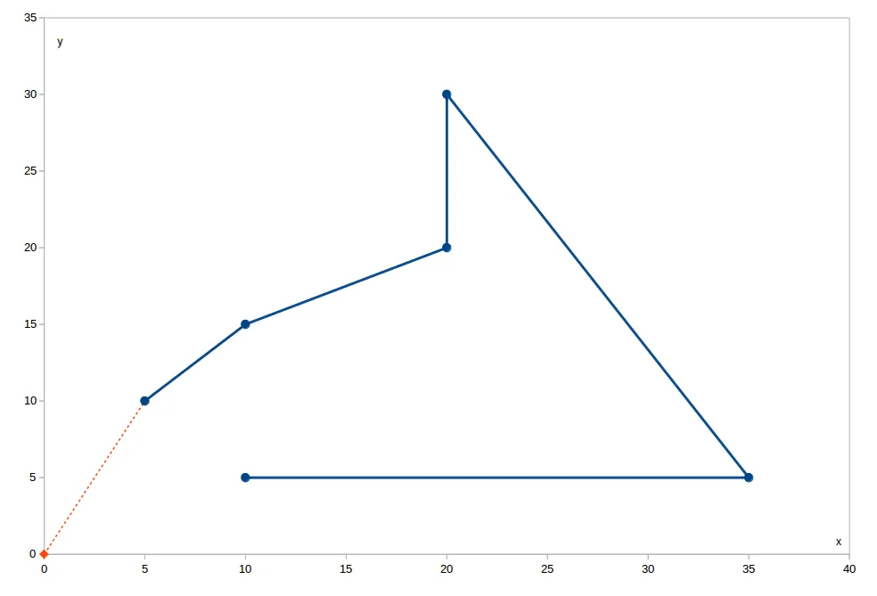
A linear move can be made with two commands. The first is G0, a rapid move to the given point. The machine goes there at its maximum speed, regardless of the set working feed rate. The second is G1, where the move is made at the speed we define in the F variable, provided it is not higher than the maximum speed of our machine. The table below gives an example of the same move with two kinds of positioning: absolute G90 and incremental G91. Absolute simply means moving to the given point, while incremental means adding values to the previous position.
Example:
| Example for G90 | Example for G91 | Description |
|---|---|---|
| G17 | G17 | set the active plane to XY |
| G90 | G90 | absolute positioning |
| T2 | T2 | mount tool no. 2 |
| G21 | G21 | dimensions in millimetres |
| G0 X0 Y0 Z0 | G0 X0 Y0 Z0 | set the starting position |
| G91 | incremental positioning | |
| M3 | M3 | spindle on clockwise |
| S3000 | S3000 | spindle speed 3000 rpm |
| F1000.0 | F1000.0 | feed rate 1000 mm/min |
| G0 X5 Y10 | G0 X5 Y10 | rapid move to X=5 mm, Y=10 mm |
| G1 Z-5 | G1 Z-5 | move the Z axis down 5 mm |
| G1 X10 Y15 | G1 X5 Y5 | milling at the set feed rate |
| G1 X20 Y20 | G1 X10 Y5 | … |
| G1 Y30 | G1 Y10 | … |
| G1 X35 Y5 | G1 X15 Y-25 | … |
| G1 X10 | G1 X-25 | … |
| G80 | G80 | cancel the milling cycle |
| T0 | T0 | move the Z axis to the zero position |
| M2 | M2 | end the program, turn off coolant and spindle |
2.2. Milling a circle or an arc
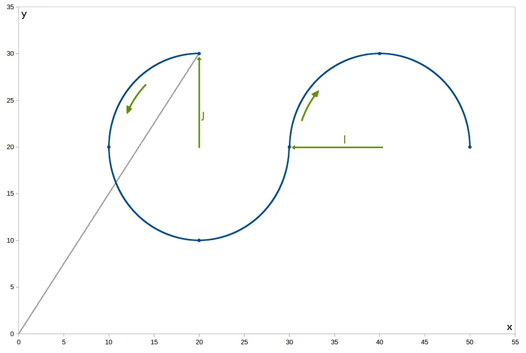
First we define the plane we are working in, then the start point of the milling and the end point, together with the distances from the start point to the centre of the circle. The variables representing the distance to the centre of the circle are denoted by a separate letter for each axis: I for the X axis, J for Y and K for Z, as below:
- G17 – X, Y, I, J
- G18 – X, Z, I, K
- G19 – Y, Z, J, K
Example 1:
| G-code | Description |
|---|---|
| G17 | set the active plane to XY |
| T5 | mount tool no. 5 |
| G90 | absolute positioning |
| G21 | dimensions in millimetres |
| G0 X0 Y0 Z0 | set the starting position |
| M4 | spindle on counter-clockwise |
| S5000 | spindle speed 5000 rpm |
| F300.0 | feed rate 300 mm/min |
| G0 X20 Y30 | rapid move to X=20 mm, Y=30 mm |
| G1 Z-5 | move the Z axis down 5 mm |
| G3 X30 Y20 J-10 | from the current spindle position, draw an arc with a radius of 10 mm and its centre at X+I=20+0=20 mm and Y+J=30-10=20 mm, to the point X=30 Y=20 |
| G2 X50 Y20 I10 | from the current spindle position, draw an arc with a radius of 10 mm and its centre at X+I=30+10=40 mm and Y+J=20+0=20 mm, to the point X=50 Y=20 |
| G80 | cancel the milling cycles |
| T0 | move the Z axis to the zero position |
| M2 | end the program, turn off coolant and spindle |
On newer machines the same can be done with a single variable, R.
Instead of:
G0 X20 Y30
G1 Z-5
G3 X30 Y20 J-10
use the following form:
G0 X20 Y30
G1 Z-5
G3 X30 Y20 R10
where R is simply the radius of the circle, here 10 mm. To draw a full circle, it is enough to give the same point as the starting point, or to give no point at all in the G2 and G3 commands:
G0 X20 Y30
G1 Z-5
G3 X20 Y30 J-10 (or G3 J-10)
Example 2:
| G-code | Description |
|---|---|
| G18 | set the active plane to XZ |
| T1 | mount tool no. 1 |
| G90 | absolute positioning |
| G21 | dimensions in millimetres |
| G0 X0 Y0 Z0 | set the starting position |
| M3 | spindle on clockwise |
| S5000 | spindle speed 5000 rpm |
| F300.0 | feed rate 300 mm/min |
| G0 Y44.14 Z44.14 | rapid move to Y=44.14, Z=44.14 |
| G2 Y15.86 Z15.86 I-14.14 K-14.14 | from the current spindle position, draw an arc with a radius of 20 mm and its centre at Y+J=44.14-14.14=30 mm and Z+K=44.14-14.14=30 mm, to the point Y=15.86 Z=15.86 |
| G80 | cancel the milling cycle |
| T0 | move the Z axis to the zero position |
| M2 | end the program, turn off coolant and spindle |
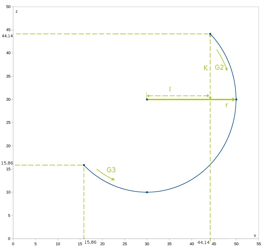
The operation can also be done the other way round. Instead of clockwise:
G0 Y44.14 Z44.14
G2 Y15.86 Z15.86 J-14.14 K-14.14
Counter-clockwise:
G0 X15.86 Y15.86
G3 Y44.14 Z44.14 J14.14 K14.14
Or another notation:
G0 Y15.86 Z15.86
G3 Y44.14 Z44.14 R20
2.3. Drilling operations
Simple drilling cycle – the syntax looks like this:
G81 X~ Y~ Z~ A~ R~ L~
Variables: X, Y, Z, A are of course the machine position, R is the safe clearance height, and L (loop) is the number of times the drilling operation is repeated at the same point. The drill plunges straight to the full depth and retracts to the safe clearance position. Nothing more.
Drilling cycle with dwell – after plunging into the material, the cutter stops for a set time.
G82 X~ Y~ Z~ A~ R~ L~ P~
The variables are the same as in the previous G81 cycle. P is the dwell time in seconds. It matters because on the last drilling pass it lets the chip be cleanly cut off from the bottom of the hole. This function is used mainly when the bottom of the hole must be machined accurately. It is also important when the hole depth is toleranced. In this case you can also use the G04 command, which lets you define the number of plunges in the Z axis. This is useful, for example, for clearing material out of the hole, so-called chip breaking.
Peck drilling cycle and its syntax:
G83 X~ Y~ Z~ A~ R~ L~ Q
Q tells the machine how far the drill advances each time until it reaches the Z value. After each plunge the drill retracts to the safe clearance point, Z or R, depending on the following parameters:
- G98 – return to the initial plane Z
- G99 – return to the reference plane R
The P option for briefly pausing the drill is missing here. The solution to this problem is in example 3.
Example 1:
This is peck drilling in the XY plane at three points: X11 Y10, X21 Y10 and X21 Y20. The maximum depth is -5 mm, with 3 passes of Q=2 mm. The last, third pass goes down only 1 mm so as not to exceed the maximum depth set in Z. The drill retracts and rapidly moves to the Z point thanks to the G98 definition, so the R parameter does not matter here. G80 cancels the drilling function.
T3 M06 G43
G17 G90 G21
G00 X11 Y10 S7000 M03
Z5
G83 Q2 G98 X11 Y10 Z-5 R2.5 F1000
X21 Y10
X21 Y20
G80
T0 M06 M02
Example 2:
This is drilling to a depth of 5 mm with a dwell of 0.1 s. The drilling positions are the same as in example 1. All the commands were described in section 2.1.
T3 M06 G43
G17 G90 G21
G00 X11 Y10 S7000 M03
Z5
G01 Z-5 F1000
G04 P0.1
G00 Z2.5
X21 Y10
G01 Z-5
G04 P0.1
G00 Z2.5
X21 Y20
G01 Z-5
G04 P0.1
G00 Z2.5
T0 M06 M02
A simpler way to write the above example, using the G82 function:
T3 M06 G43
G17 G90 G21
G00 X11 Y10 S7000 M03
G82 Z-5 G99 X11 Y10 R2.5 P0.1 F1000
X21 Y10
X21 Y20
G80
T0 M06 M02
Example 3:
And what if we are greedy and want both chip breaking and a dwell in one program? Drilling in 2.5 mm steps down to Z=-5 with a dwell of P=100 ms at three points, as in examples 1 and 2:
T3 M06 G43
G17 G90 G21
G00 X11 Y10 S7000 M03
Z2.5
G01 Z-2.5 F1000
G00 Z2.5
Z-2.5
G01 Z-5
G04 P0.1
G00 Z2.5
X21 Y10
Z2.5
G01 Z-2.5
G00 Z2.5
Z-2.5
G01 Z-5
G04 P0.1
G00 Z2.5
X21 Y20
Z2.5
G01 Z-2.5
G00 Z2.5
Z-2.5
G01 Z-5
G04 P0.1
G00 Z5
T0 M06 M02
3. Which FREE CAM programs?
There are programs written solely for specific operations, and universal engineering programs for everything. The latter have the following drawbacks: they are paid, very expensive, need a powerful computer and are complicated. To start with, we recommend simple programs for specific uses, free of course, and describe their pros and cons.
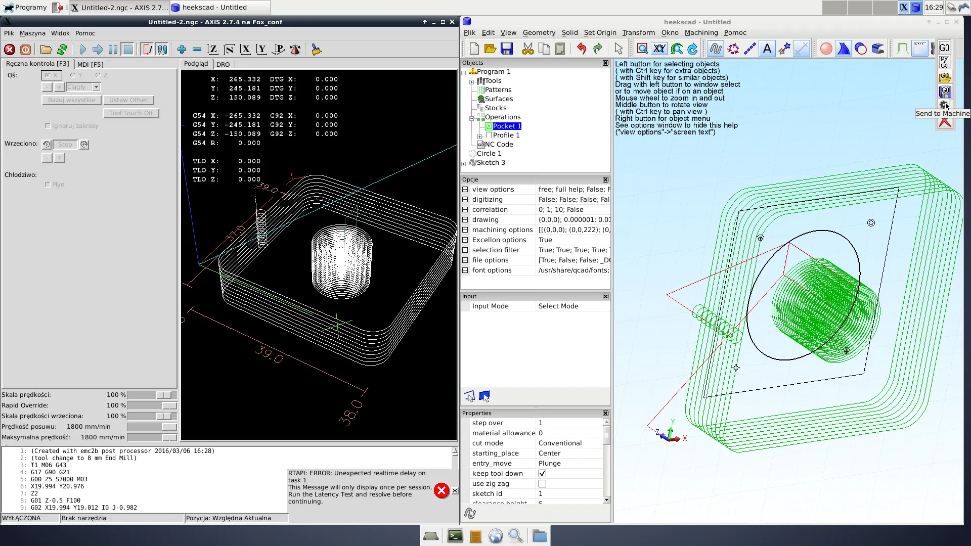
3.1. HeeksCAD – everything except engraving and turning
HeeksCAD is a functional and free CNC machining program, in a trial version. Fortunately the limitations are merely annoying (it adds comments that you have to remove from the file before milling, and it opens the home page while verifying the G-code), and they do not change the functionality of the program compared to the full version. The problem goes away if we buy it or compile it ourselves instead of installing it. It also works on Linux, and, what interests us most, with LinuxCNC. There we can send the G-code to the machine with one button. However, on Linux this option replaces the simulation, which is very useful on Windows. It is good to preview what we have created before starting work in the workshop.
What can we do in the program? Profile cutting, facing, pockets, drilling operations and 3D milling. In addition, there is the ability to draw and dimension simple solids and shapes. When machining, we can set the number of passes in the Z axis, contour machining for pockets and periodic retraction when drilling. These are some of the more important features, and there are many more options. In my opinion it is the best program for creating G-code for free in 2016. Some of the capabilities of HeeksCAD are shown in the video below.
The biggest drawbacks we have noticed:
- no gentle ramp-down on Z-axis moves, so the Z feed rate has to be set very low!!!!
- clumsy CAD design
3.2. F-Engrave – everything related to engraving
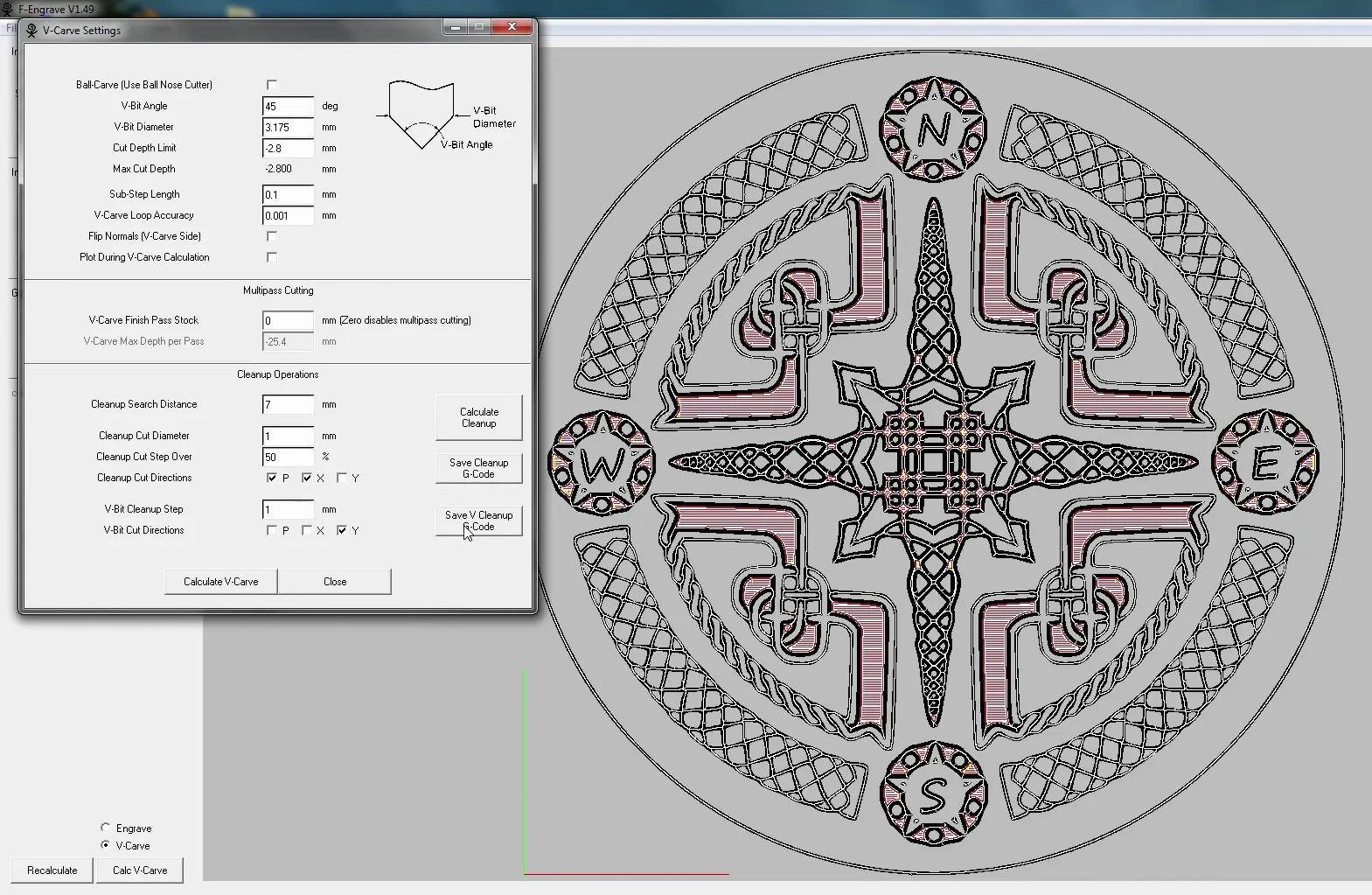
F-Engrave is a completely free program written in Python and based on engrave-11, written for LinuxCNC. To get started we need text, which we can type directly into the program, or a black-and-white image in .bmp format, or a .dxf file. The following engraving options are available:
- V-bit engraving – paths calculated for the selected cutter, plus clean-up with a flat cutter options
- B engraving – from the English “ball nose”, i.e. with a ball-nose cutter
- pocket cutting with a flat cutter
- creating inlays, i.e. two parts: a pocket and a plug
F-Engrave is certainly the best free engraving program, and a simple and stable one at that. Its biggest drawback is file handling: files must be in the right format, especially dxf. It supports BMP only when saved in 24-bit format.
Video: creating G-code in F-Engrave
3.3. Dmap2gcode – bas-reliefs from grayscale images
Another scorchworks program after F-Engrave: Dmap2gcode. It is written in Python and based on image-to-gcode, implemented in LinuxCNC. It lets us convert a grayscale image into a 3D object. Depending on the shade of gray of a point, a plunge depth in the Z axis is assigned to it. Unfortunately, it is quite hard to create an image that reproduces what we want to get. The program could use a visualisation of the resulting effect.
3.4. DXFhalftone – images from halftones
DXFhalftone is an easy-to-use free program for creating images from dots or lines of various sizes. The image is clearly visible from a certain distance, while up close you can see tightly packed holes. The code can be generated from any jpg, png or gif image. The effect is created by spacing the holes differently depending on the contrast level. The code can be saved in formats understood by CNC machines, as well as in dxf format.
Such images are best made on thin, matte, light-coloured sheet metal or on solid boards with a coating (laminate) in a contrasting colour. Besides artistic uses, these plates can be used as, for example, a fan cover, decorative ventilation openings, fences, gates and so on.
Video: halftone image with DXFhalftone
3.5. Other programs worth recommending
Gcoderipper – a free program written in Python by scorchworks that lets you load and edit G-code. The program offers the following capabilities:
- scaling G-code
- rotating G-code
- splitting G-code
- converting 2D and 2.5D code to a rotary axis (the fourth axis)
- changing the zero position
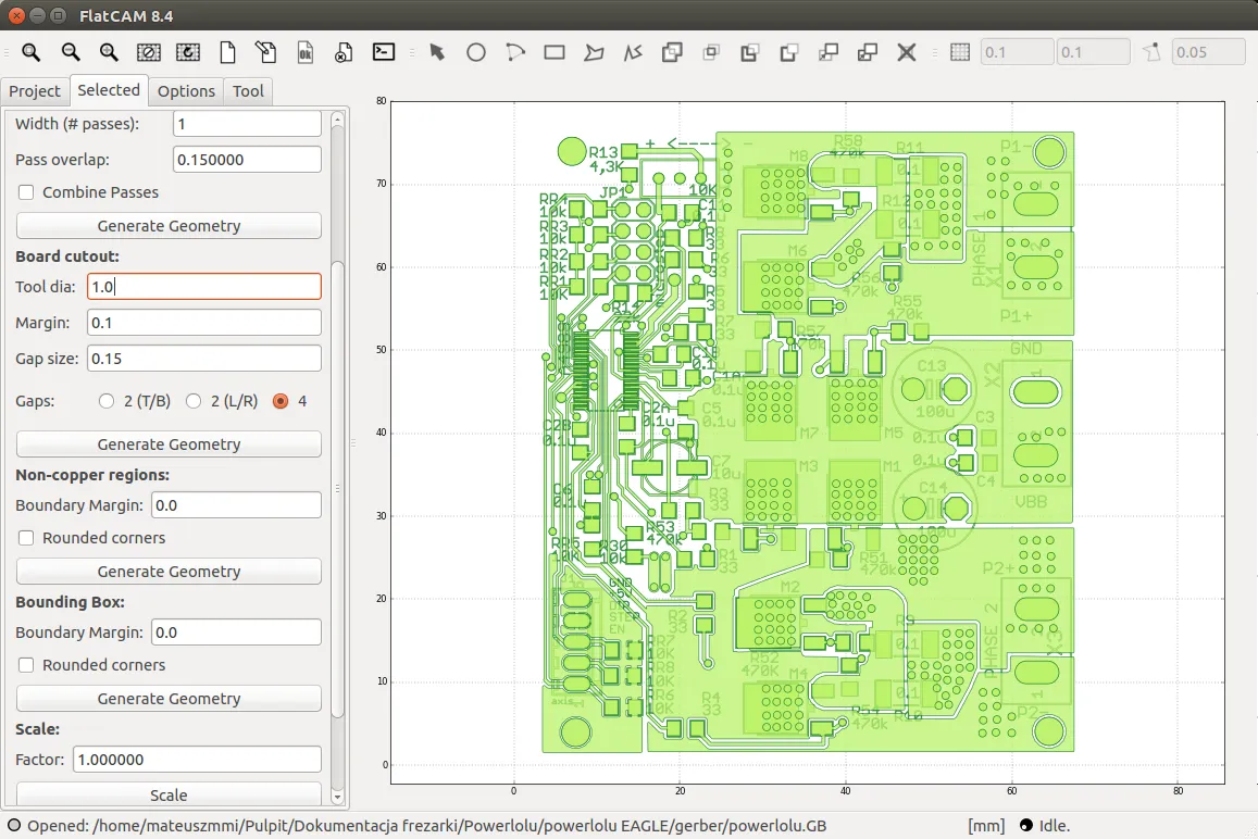
FlatCAM – lets you edit and create printed circuit boards on a CNC machine. It supports projects saved in the Gerber format. A useful tool for electronics people. HeeksCAD can also open such files; it does not read them correctly, but somehow it reads them :D. The program is of course written in Python. It is especially useful for milling the isolation between traces and for drilling holes. The program works on all operating systems. The interface is oddly designed and it is easy to get lost in it.
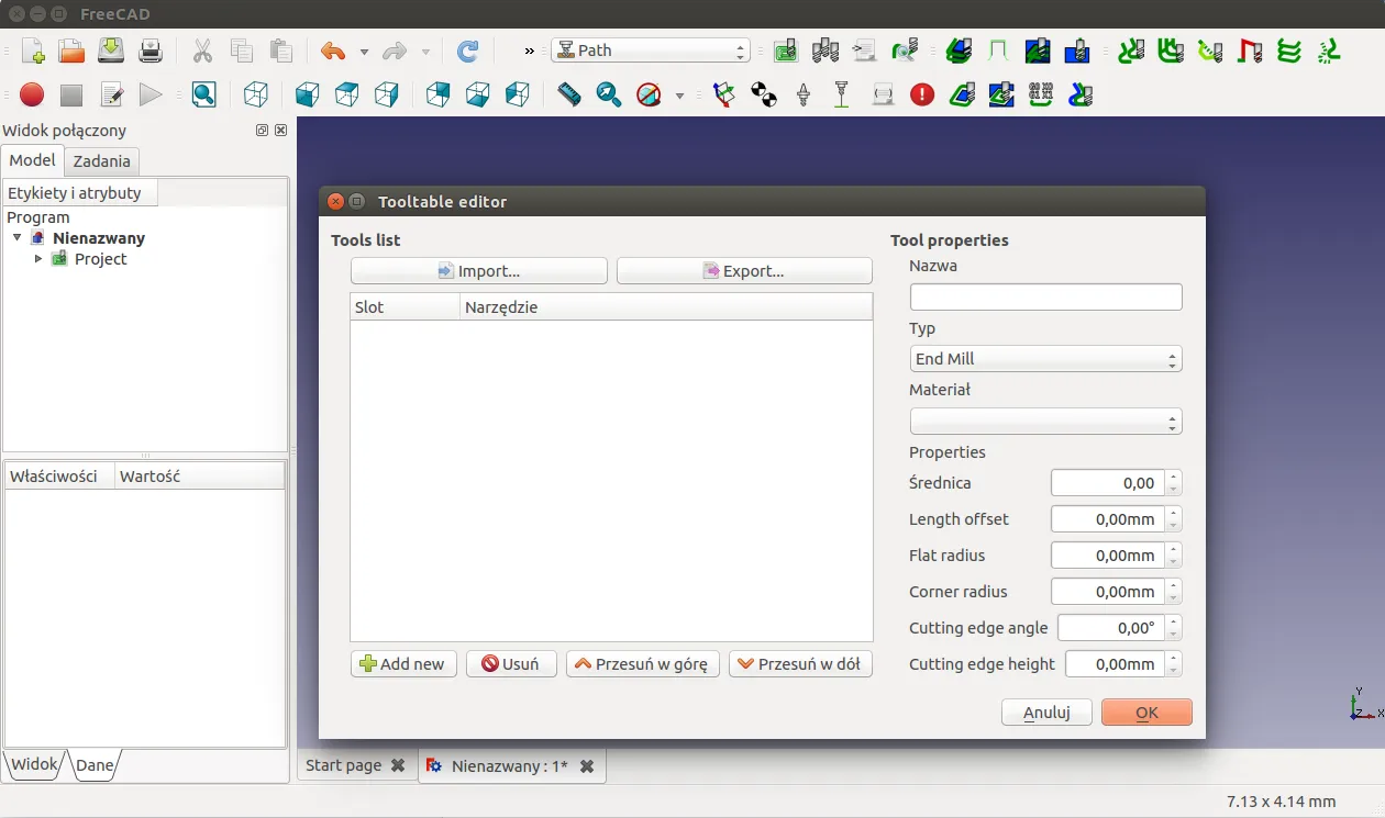
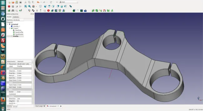
FreeCAD – a free program mainly for modelling. It can, however, create G-code in the “Path” tab. This sub-program is constantly being modified and is not fully functional, but you can see it has potential. The FreeCAD Path Workbench documentation describes the tools in the Path tab, visible in the upper right part of the picture below.
A longer list of free programs, not only for CNC but also for lasers, plus conversion and simulation programs, can be found on this page: http://www.shapeoko.com/wiki/index.php/CAM.
3.6. Programs we do not recommend
Pycam – generates G-code automatically for 3D objects. It has few settings, and generating the code itself takes many hours and is very resource-hungry.
FreeMill – it has the adjective “free” in its name, but only the really basic and useless options are free. Instead of paying for the full version of the program, I recommend supporting the HeeksCAD project.
4. Free modelling of objects for 2D and 3D milling
Simple moves and cutting can of course be written by hand directly as G-code, but more complex ones can take us forever. Naturally, our object should be drawn in electronic form. And here it depends on what and in which program. For simple 2D things and so-called 2.5D, an outline is enough, while 3D needs a full model. So what should we use?
4.1. HeeksCAD
First of all, this very program. The modelling is clumsy and advanced models are really hard to make, but simple things are fine. We can generate G-code in it straight away and send it to the machine. The program also has simulation options, but for some reason only on Windows. The download link is here: HeeksCAD. Below we list everything that can be modelled with the program:
- drawing simple shapes: lines, rectangles, ovals (bean shapes), polygons and gears with any number of teeth
- drawing curves: through 3 points, centre and point, centre and radius, and ellipses
- drawing points: infinite line, points, curve through points (spline)
- dimensioning, text
- transformations: scaling, rotating, mirroring, etc.
- drawing 3D shapes: sphere, cube, cylinder, cone
- extruding and revolving shapes, etc.
- intersection, fusion and cutting of shapes
- chamfering, filleting
4.2. Inkscape
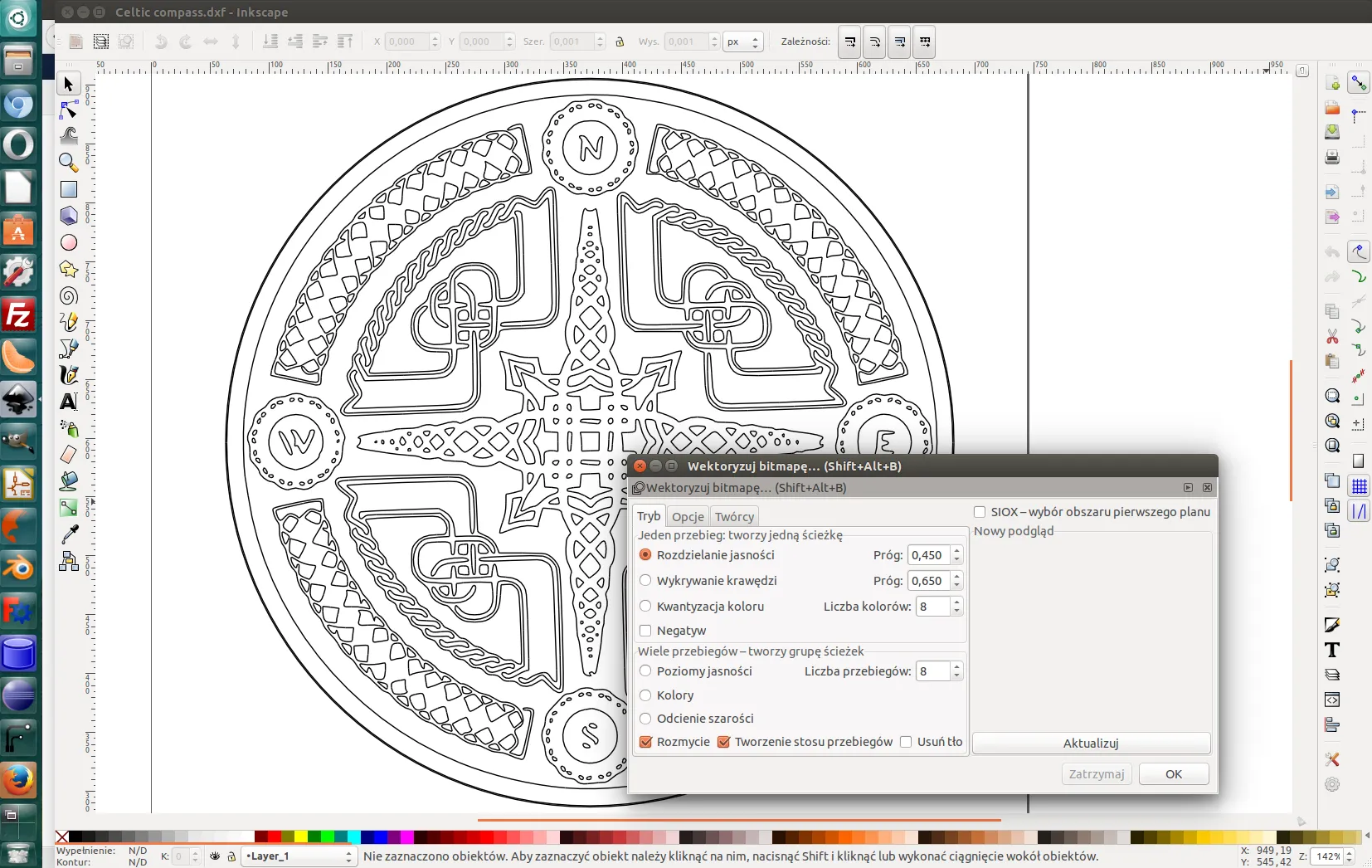
Inkscape is a vector graphics program, a free alternative to CorelDraw. We create models in dxf format, of course only 2D, but that is entirely enough for most projects. From a dxf file, by defining the milling depth, we make 2.5D objects. Models for HeeksCAD have to be dimensioned in pixels, not mm.
A very useful feature here is bitmap tracing. Once we have an image downloaded from the internet or drawn by us in raster graphics, we can easily convert it to a vector format. Most CAM programs support it.
4.3. FreeCAD
More advanced than HeeksCAD, and it also has the ability to create G-code (at the time of writing still a beta version). You can model and dimension even very complex models in full 3D. The program is a free equivalent of AutoCAD or Solid Edge.
4.4. Gimp
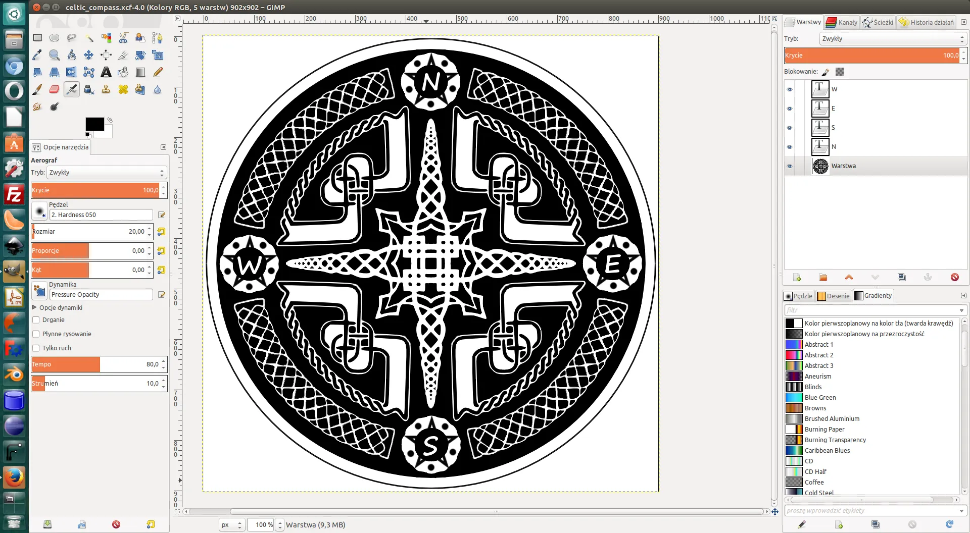
Gimp is a free, advanced program for raster graphics. It is useful mainly for CAM programs such as F-Engrave and Dmap2gcode. With it we can prepare complicated, mostly decorative and artistic images. After such preparation we can create G-code directly in programs that import these formats, or convert the images to vector graphics in Inkscape or Corel Draw. In section 3.2 there is a demo video in which we process a Celtic compass graphic and create the code in F-Engrave. For bourgeois types or pirates we recommend Adobe Photoshop.
4.5. Blender
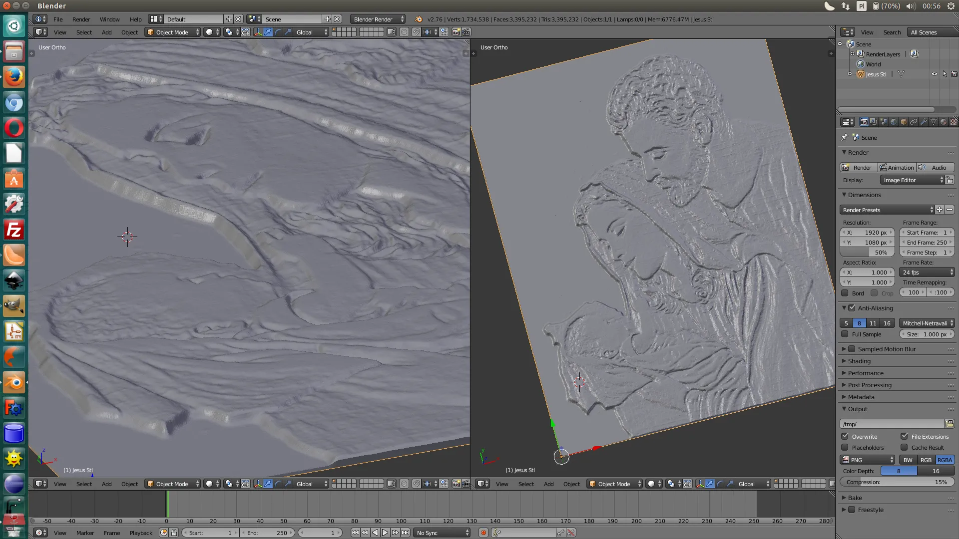
Blender is the best free program for artistic modelling of 3D objects. It has huge capabilities for creating 3D objects, all described on the Blender features page. It is poorly suited to parts that must be precisely dimensioned or are typically engineering parts. With it, after a longer training, e.g. on YouTube, we will be able to make models for bas-reliefs. We save the files in stl format, which can be processed in HeeksCAD or printed on any 3D printer. The picture below shows very clumsy attempts at modelling a bas-relief. It takes more than a few days of learning, though.
5. Paid programs
If none of the programs listed above meet our requirements, we cannot achieve our goals with them, or we own a machine more advanced than a 3-axis one, then we have to use paid programs. 2D and 2.5D models can be made fairly quickly and easily in any program, while full 3D takes more practice and a longer acquaintance with three-dimensional modelling. Without this skill we will not be able to make any complex part. Modelling differs depending on the kind of products we make.
Engineering modelling – where it is important to dimension the part exactly: its height, width, radius, exact positions of holes, notches and so on. Engineering programs require creating the part with exact dimensions, and for that we need a suitable CAD. As we wrote, there are free ones, such as FreeCAD, and paid ones, such as Solid Edge and AutoCAD, as well as CAD/CAM suites such as Siemens NX, BobCAD-CAM or Catia. The latter are very resource-hungry and complicated, but they support even five-axis machines. Besides, the average hobbyist mortal will not be able to afford a licence. The cost is somewhere between the high tens and low hundreds of thousands of zlotys, for incomplete versions.
Artistic modelling – where the dimension is not important, only the proportions, and the part itself can be scaled freely. Examples are bas-reliefs and all kinds of 3D decorations. For artistic tasks we will need a model. If we do not want to commission this work from someone else, or cannot find ready-made models to download, we will have to create them ourselves. A program such as ArtCAM from Autodesk will help. It is used for machining wooden parts. It lets us create a 3D object from a flat image or an outline, by extruding, bending, bulging and so on. Very useful for people with no experience of 3D modelling. A similar program is BobArt. The best results are achieved by creating models in CAD programs designed for 3D models (Blender, 3ds Max, etc.), especially those meant for 3D printers.
Models for specialist applications – CNC mills have many uses in medicine, jewellery, dentistry and industry. Models are also created in various ways: in specially designed programs, by scanning objects, and others. Let us not go into that.
6. Summary
When it comes to CAM/CAD programs, we do not need to worry: there are really a lot of them, we have not described them all, and many more will certainly appear. If we insist and work purely as amateurs, we can do everything we want with free software. All of this, of course, on a 3-axis machine.
- For mechanical parts, the following programs are enough: Inkscape or FreeCAD, and then HeeksCAM, in most cases just HeeksCAD itself.
- For engravings and inlays: Gimp or Google (or some other search engine), and F-Engrave to create the code. If we only want to engrave a simple text, F-Engrave alone is enough.
- Maybe some halftone? We will use Gimp, a web search engine and DXFHalftone.
- A bas-relief? This is where it gets harder, but the ambitious sit down and learn Blender and do the machining in HeeksCAM. The less ambitious buy ArtCAM.
- Into electronics and making PCBs? We recommend the free FlatCAM.
Do you recommend other programs? Do you know any other amateur uses of a CNC machine? Tell us everything in the comments.