
Installing and Configuring LinuxCNC with StepConf
Originally written in Polish and translated into English.

LinuxCNC is completely free software for controlling CNC machines, lathes and the like. For beginners and garage hobbyists it is a must-have. In this article we only describe the basics of installation, since there is plenty of material about it online and it shouldn’t cause any problems. We focus more on configuring stepper motors and preparing the machine for its first cut. LinuxCNC also supports servo motors, but unfortunately we haven’t had a chance to play with them yet.
1. Installing LinuxCNC
At http://www.linuxcnc.org/index.php/english/download you will find an .iso file with a complete Debian operating system. It contains LinuxCNC, a completely free program for controlling CNC machines: machine tools, plotters, robot arms and so on. Installation is trivial and described in the documentation. We wrote the .iso file to a USB stick with Win32DiskImager. Then comes some fun in the BIOS with the boot order (boot manager): we select USB and our removable drive. We save the settings, restart the computer and choose the “graphical” installation mode. Next we set the system language and the internet connection (this can be skipped), choose the disk to install on (preferably a whole empty partition) and click Next until the installation starts. After that we change the boot order back to the hard disk. Once the system is running, we connect to the internet and install the updates.
We can run two operating systems side by side without any problem. Windows or macOS must be installed first. Linux will then add GRUB, the screen where you choose the operating system. By default, if you don’t click anything within a few seconds, LinuxCNC starts. The order can be changed in the configuration files.
Do not upgrade the system to a newer release. If you do, our program will stop working. Install only new versions of programs and security updates!
The last step is recovering the space on our USB stick, which suddenly lost its original capacity (that happens when you write an .iso to it). We do this in the freshly installed Linux. Open a terminal emulator from the Applications bar and type:
sudo apt-get install gpartedAfter you enter the administrator password, gparted, a disk partitioning program, will be installed under Applications/Accessories. Open it, enter the administrator password again, select our drive in the upper left corner, delete all partitions and create one partition of maximum size formatted as fat32. Apply the changes and we are done. Now we can move on to configuring LinuxCNC.
2. Configuring LinuxCNC
To adapt LinuxCNC to our machine we have to go through the configuration with CNC/Stepconf. It is in the LinuxCNC menu. At the start a window opens where we can choose between creating a new configuration or editing an existing one. We can also tick the options to create shortcuts to the configuration folder and to a launcher with the configuration we set up.
Next we get to the basic machine settings. Here we enter its name, the number of axes and the units we will use, mm or inches. Below are the driver settings. We pick our type from the list, and if it isn’t there, we enter its data manually. Our driver is a Pololu based on the A4989 chip, which is not on the list. In the chip’s datasheet we find all the timings of the signals that control the motor movement.
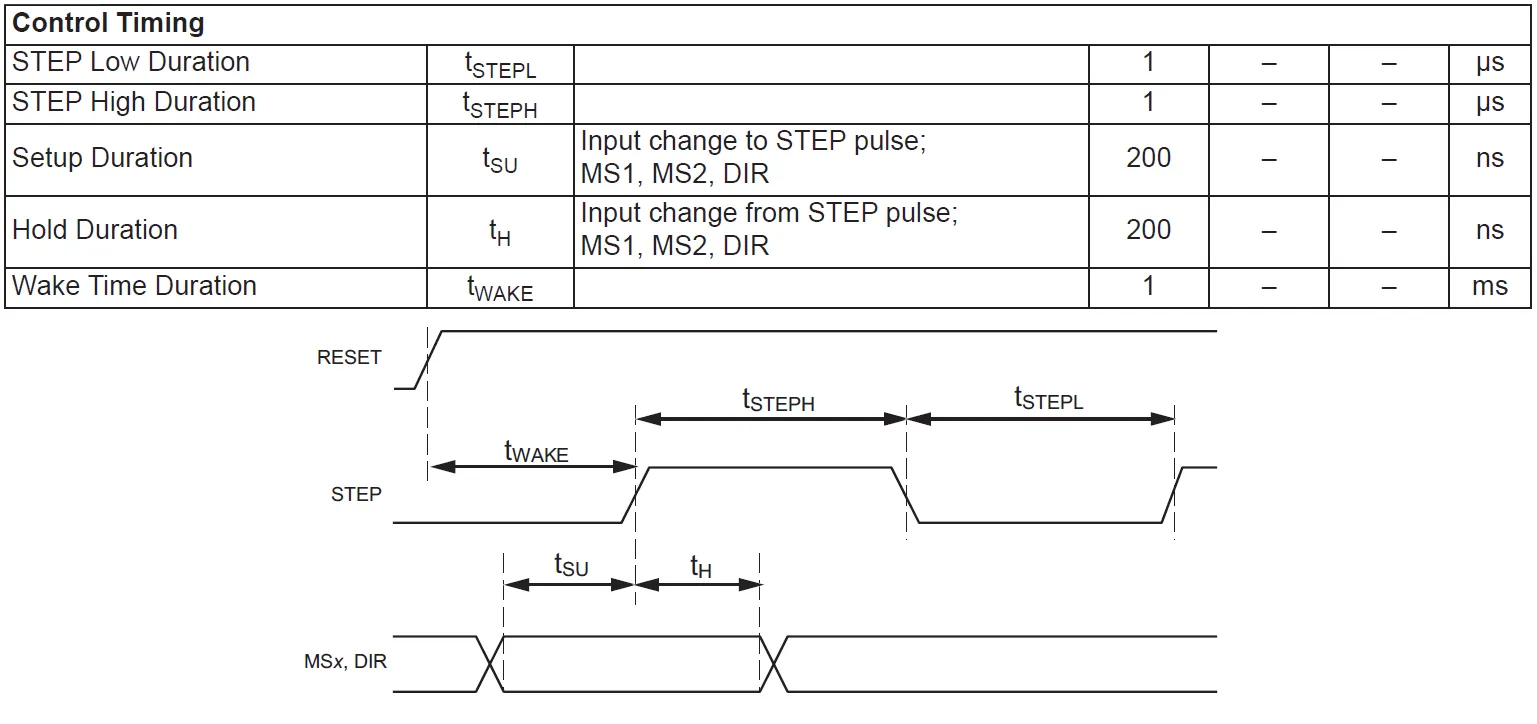
Figure 1. Switching times of the STEP and DIR signals
There are four fields to fill in:
Step Time – how long the step pulse lasts, depending on whether we set it active-high or active-low. For our driver it is 1000 ns.
Step Space – the minimum time between step pulses, in our case the duration of the low state. Again we enter 1000 ns from the table.
Direction Hold – how long the direction pin keeps its state after the direction signal changes. In the datasheet it is Hold Duration and equals 200 ns.
Direction Setup – how much time is needed to change direction after the last step change. In the documentation, Setup duration is 200 ns.
Next we choose the number of parallel ports used. We have one, so we tick One parport.
The last item in this section is the base period maximum jitter. It is an odd name, but it is about how quickly the computer can interrupt whatever it is doing and respond to a request. To obtain this value we run a measurement with the Test button. During the test we load the computer: we run basic programs, copy files, play music and so on. Without going overboard, of course, but if we enter too low a value, our machine may go haywire, for example when the screensaver kicks in or when we move the mouse. After a few minutes of testing we note the maximum measured time. The larger this time, the lower the stepping frequency of the motor and the less smoothly it will run. The jitter depends on the configuration of our computer: the processor, motherboard, graphics card and system errors. Values below 40000 ns are a good result, and much larger times disqualify our computer.
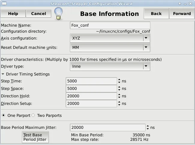
Figure 2. Basic information in the Stepconf settings
With all the parameters entered, we move on to the parallel port configuration. We have 17 outputs and 5 inputs to assign. That many pins is entirely enough for a simple machine, even a 4-axis one. At minimum we need two outputs per axis for step and direction, a signal to switch on the power, spindle on and coolant, or possibly a chip vacuum. As for inputs, we use at least two: one for all the limit and home switches, and the ESTOP input.
-
ESTOP is an electronic emergency stop. It does not cut the power completely, it only halts the program. We recommend adding a real emergency button that disconnects power to the whole machine in case the system or program hangs, or the motherboard input fails.
-
Limits are simply limit switches. Reaching any of them stops the program. We will not be told which one, unless we set three inputs as the X, Y and Z limits. That is not very useful, because we can see visually when an axis reaches its limit.
-
Homing is, put simply, searching for the axis origins, that is the zero points. One input is enough, and it is shared with the limit switches. How does homing work? There are two options: homing a selected axis or all axes at once. The computer knows which axis is being homed and which switch it should travel to. By default (depending on the settings later in Stepconf) it goes like this:
- the axis starts moving in a certain direction
- it travels until it hits the switch
- it backs off, and the moment the switch opens is marked as the starting point
- the declared axis length (set later in Stepconf) is added to the starting point
After this the program knows where the limits are, and however hard we tried, we could not trigger the limit switch. Reaching it will simply stop the movement without stopping the program. From then on the limit switches are just a safeguard in case of, for example, a lost step or the axis being shifted somehow.
There are also options to invert a signal, in case something works the wrong way round.
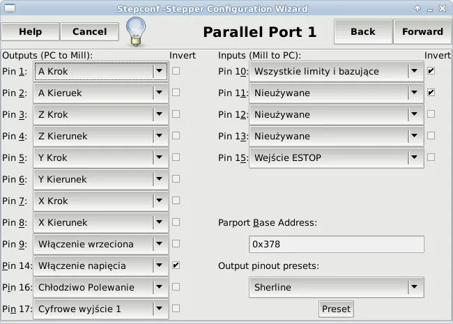
Figure 3. Axis configuration
3. Axis configuration
Motor Steps Per Revolution – the number of full steps the motor makes in one revolution. Our 57h76-3008b motor has a step angle of 1.8 degrees. So: 360/1.8 = 200 steps.
Driver Microstepping – we set the driver with jumpers to divide each step by 16, so we enter 16.
Pulley Ratio – if the machine has a gear or belt reduction, enter its ratio as motor gear:axis gear. Ours has none, so the ratio is 1:1.
Leadscrew Pitch – enter the pitch of the drive screw or belts here. Our axis on a trapezoidal screw has a pitch of 4 mm/revolution. If the machine moves in the wrong direction, you can enter a negative value.
Maximum Velocity – we choose this value from calculations or by trial and error. We set ever higher speeds and, while testing the axis, check whether the motor loses steps under load. We can simulate the load by pushing the axis by hand against its direction of motion.
Maximum Acceleration – here again we can try to calculate the maximum acceleration, but we still have to test it in practice. As before, we find the value experimentally, increasing it gradually. We click the Test this axis button, enter the speed and acceleration and the travel value in the test area, and click Run. The axis will move in both directions while we add load ourselves. We look for the maximum values of these two parameters at which the motor does not lose steps.
Home Location – the position in space of the axis origin. After homing, the axis will be set to this point, zero by default.
Table Travel – here we enter two points in space that define the travel range of our axis. The home location must lie inside this range and must not be equal to either of the two values. If our axis has a maximum travel of 0.5 m, we enter values such as 1 and -499 mm. Then the home position can be 0. In practice the program corrects incorrectly entered values by itself.
Home Switch Location – the position the axis moves to during homing. The value must not be the same as for the limit switch if they work together. With an incorrect configuration we get the error: joint limit error.
Home Search Velocity – this value defines the speed of approach to the switch during homing. Set it slightly lower than the maximum (unless the maximum is small :)) so the motor has time to slow down before the limit. If the axis moves in the wrong direction, simply enter a negative value.
Home Latch Direction – there are two options:
- Same – after reaching and closing the switch, the axis backs off and enters it again at low speed. When the switch closes again, the starting point is stored.
- Opposite – after reaching and closing the switch, the axis slowly backs off. When the switch opens, the starting point is set.
Below that we get information about the figures our machine can achieve:
Time to accelerate to max speed – the time needed to reach maximum speed, calculated from the maximum acceleration and velocity entered.
Distance to accelerate to max speed – the distance the axis travels from standstill to maximum speed.
Pulse rate at max speed – the frequency sent to the motor at maximum speed.
Axis SCALE – the number of motor steps per millimetre of movement. This value is used to scale the speed.
Test this axis – opens a window to test the motor parameters we have entered.
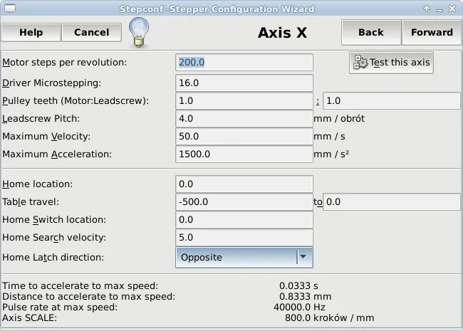
Figure 4. Configuration window of the X axis
And so our program is correctly configured and we can start having fun with machining. It is also worth making a few modifications that make working with the system easier. You can find more about that in the article Basic Changes in LinuxCNC.