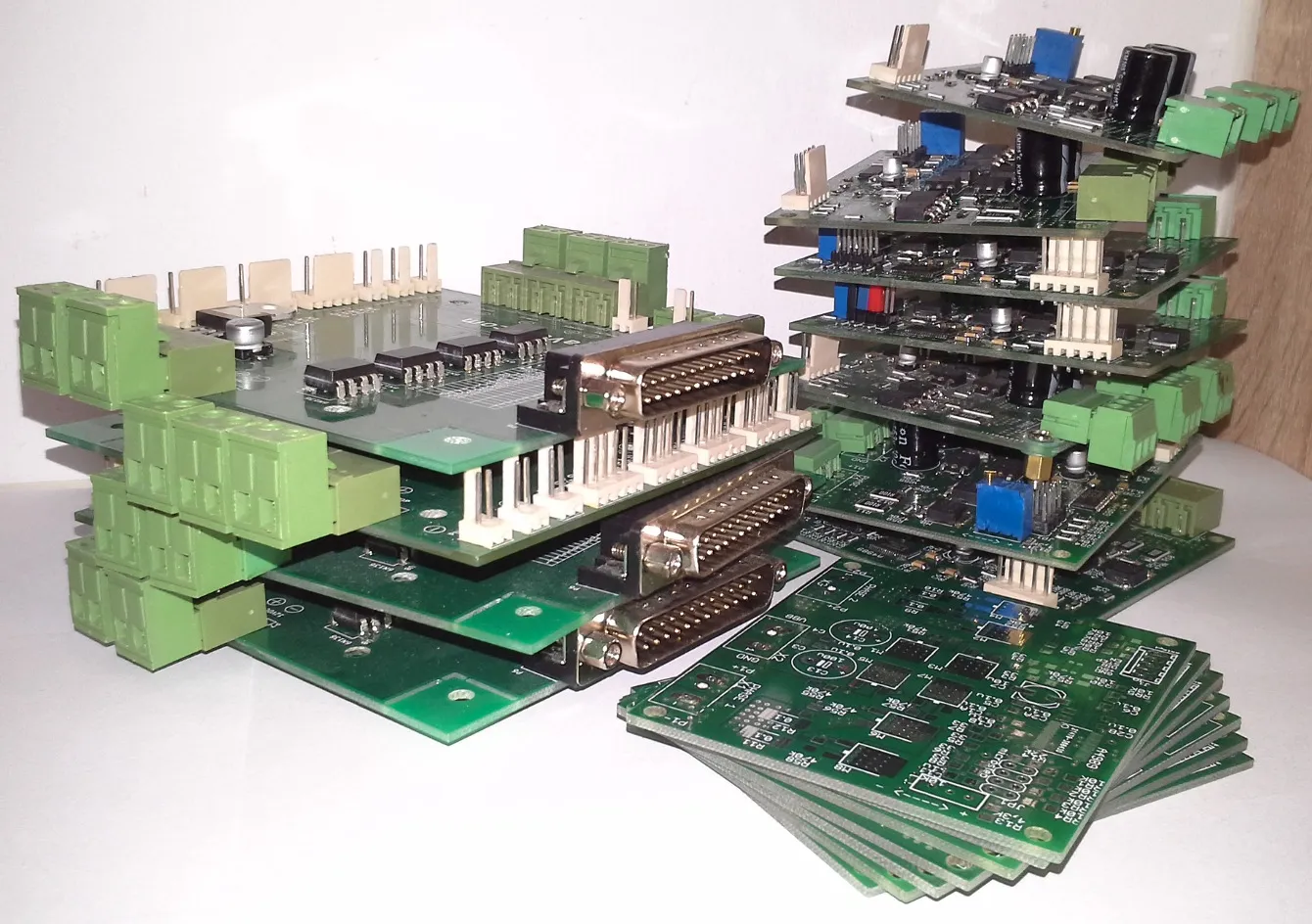
CNC Mill Electronics: Power Supply, Stepper Drivers, LPT Board
Originally written in Polish and translated into English.
Contents
In this article we describe a complete controller for a CNC mill used for machining wood, plastics and soft metals. In our application it drives a 3-axis mill, but it can easily be extended with an additional axis. The stepper motors are driven by Allegro A4989 chips. All the electronics are managed by LinuxCNC running on Debian. The modules presented in the article are prototypes and we are still modifying them.
1. General description of the control system
The mill’s control box consists of the modules shown in Figure 1:
- power supply: transformers and power supply units
- main board
- output modules
- stepper motor drivers (Powerlolu)
We use 4 voltage levels in the project:
- 230 V to power the outputs and the transformers
- 5 V to power the TTL logic
- 12 V for relays and future uses
- 45 V to power the stepper motors
The main board protects the output and input elements against damage and sets the appropriate voltage levels using Schmitt triggers. It provides optoisolated inputs and outputs for connecting any modules, e.g. with a triac or a relay (to control the spindle, coolant and any other accessories for the mill).
The Powerlolu boards can drive motors with a rated current of up to 10 A and high torques, which is ideal for heavy loads. Each motor step can be divided into up to 16 microsteps, which allows precise positioning and smoother operation. A more detailed description of the modules is given later in the article.
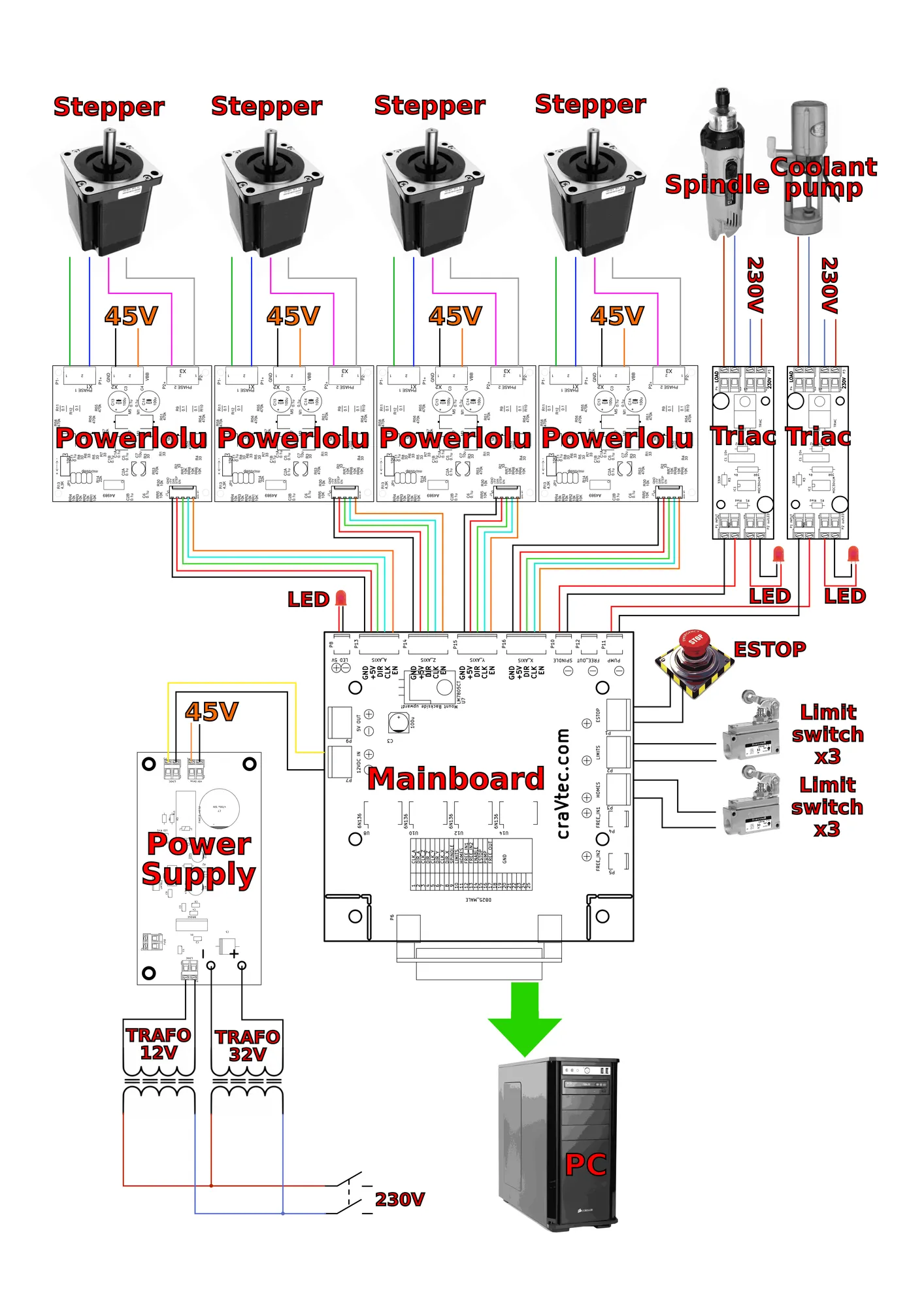
Figure 1a. Example connections between the modules
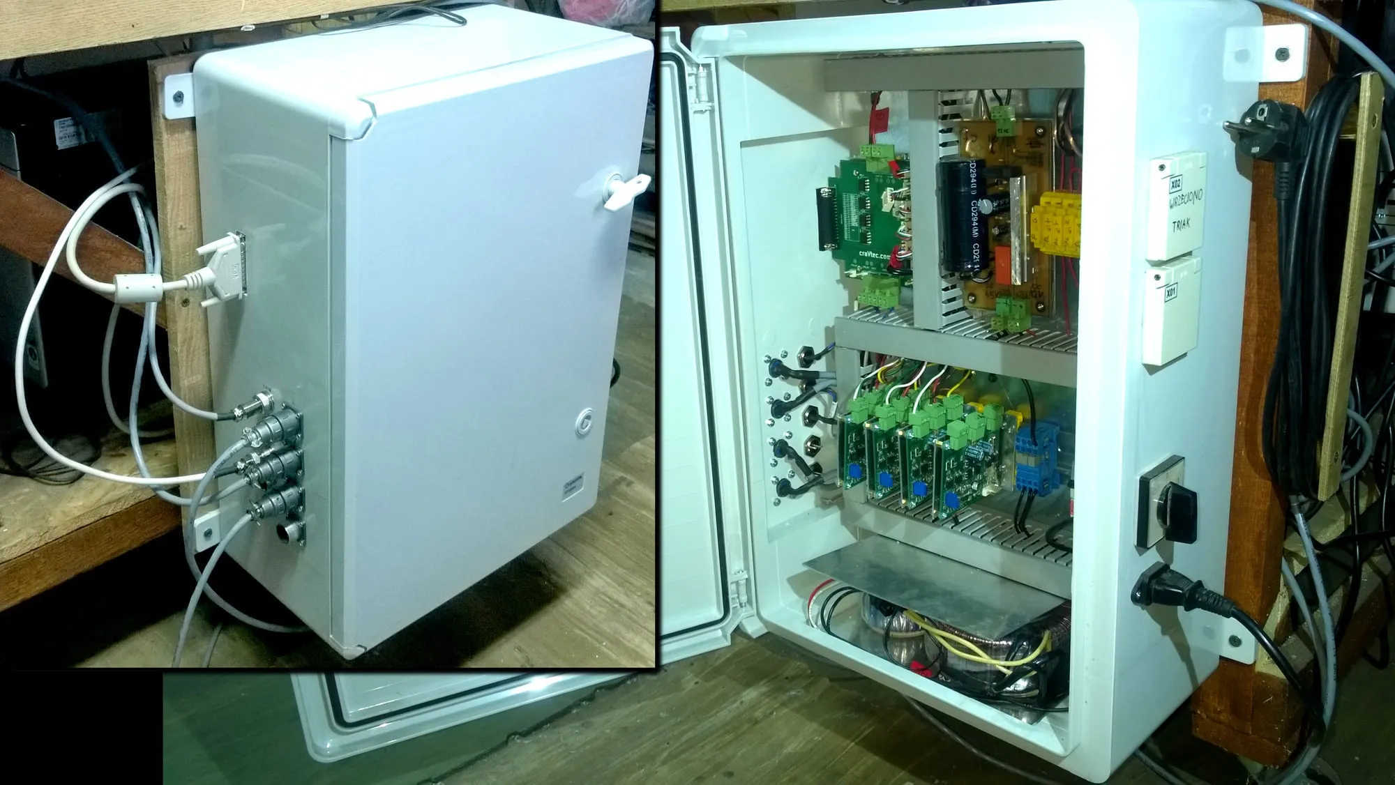
Figure 1b. Photo of the control box
2. Power supply
The machine is powered by two toroidal transformers. The first one, 12 V/5 A, gives a DC voltage √2 times higher after rectification and filtering with a 4700 uF/25 V capacitor, i.e. about 17 V. From this we get a stabilised 12 VDC using an LM7812. The second toroid, 32 V/12.5 A, powers the stepper motors without stabilisation. After rectification and filtering with a 10 mF/100 V capacitor we get 45 VDC. When choosing the capacitors we followed the rule of 1000 uF per 1 A of current drawn. The larger the capacitance the better for the drivers, but the more expensive for the user :). Our transformers will not be loaded that heavily, so we chose capacitances slightly lower than calculated.
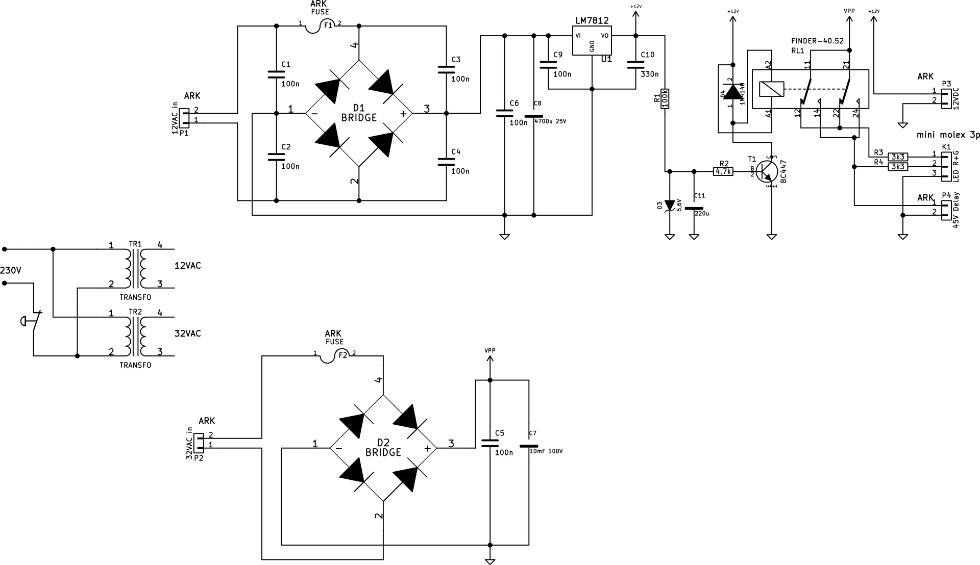
Figure 2. Power supply schematic
The power supply also has a built-in delay circuit with a relay, which delays switching on the power to the stepper motors. First, the supply voltage is applied to the main board, the red indicator LED and the delay circuit made of the electrolytic capacitor C11 and the resistor R1. By choosing suitable values of R and C you can get the required delay (the larger the values, the longer the delay). After a certain delay the circuit switches on a relay, which applies voltage to the stepper motors. A delay circuit based on an NE555 or some microcontroller would be a better solution, because in our circuit the voltage on the relay coil rises gradually. The relay contacts are then closed and opened slowly when the voltage is removed. With high currents this can cause faster wear or contact welding.
3. Main board
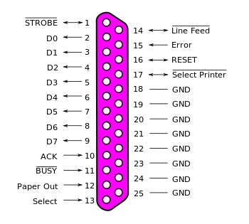
Figure 3a. LPT port signal assignment
The machine is controlled by a PC through the LPT parallel port. The specification shows that it can drive 8 outputs and 5 inputs, 4 pins can work as either input or output, and the remaining ones are connected to ground. In LinuxCNC, pins 1, 14, 16 and 17 are set as outputs, so in total we have 12 outputs and only 5 inputs available. If that does not meet your needs, you can configure two LPT ports, but for a simple machine one is enough. To configure a 3-axis machine we need at least 7 outputs: two signals for each motor (step and direction) and a signal to switch on the power. The remaining ones can be used to switch on the spindle, coolant, vacuum cleaner and so on. As for inputs, we need at least two: one is reserved for the limit switches and for homing the axes, i.e. finding the machine’s starting point. The other input must be reserved for the ESTOP emergency stop button.
How does homing work?
After you press the “home all axes” button, the machine moves each axis in turn and looks for one of the limit switches. With the program’s default settings, it drives onto the switch, then backs off, and when the contact opens it marks that spot as the starting point. From there it adds the maximum axis length declared earlier in the configuration. If we entered all the lengths correctly and the machine is configured properly, after travelling to the opposite limit switch the program will stop just before it, without triggering it.
LPT port pin description:
| Pin no. (DB25) | Signal name | LPT direction | LinuxCNC direction | Example use for 4 axes |
|---|---|---|---|---|
| 1 | Strobe | In/Out | Out | Step A |
| 2 | Data0 | Out | Out | Direction A |
| 3 | Data1 | Out | Out | Step Z |
| 4 | Data2 | Out | Out | Direction Z |
| 5 | Data3 | Out | Out | Step Y |
| 6 | Data4 | Out | Out | Direction Y |
| 7 | Data5 | Out | Out | Step X |
| 8 | Data6 | Out | Out | Direction X |
| 9 | Data7 | Out | Out | Free output 1 |
| 10 | Ack | In | In | Limit and homing switches |
| 11 | Busy | In | In | Free input 1 |
| 12 | Paper-Out | In | In | Free input 2 |
| 13 | Select | In | In | Free input 3 |
| 14 | Linefeed | In/Out | Out | Power on |
| 15 | Error | In | In | ESTOP |
| 16 | Reset | In/Out | Out | Free output 2 |
| 17 | Select-Printer | In/Out | Out | Free output 3 |
| 18-25 | GND | - | - | - |
The most important function of the main board is galvanic isolation of the input and output signals and conditioning of the motor control signals. The integrated circuits used for this are:
- PC817: standard optocoupler
- 6N137: fast optocoupler, for the motor control signals
- 74HC14: Schmitt triggers, for more reliable motor control
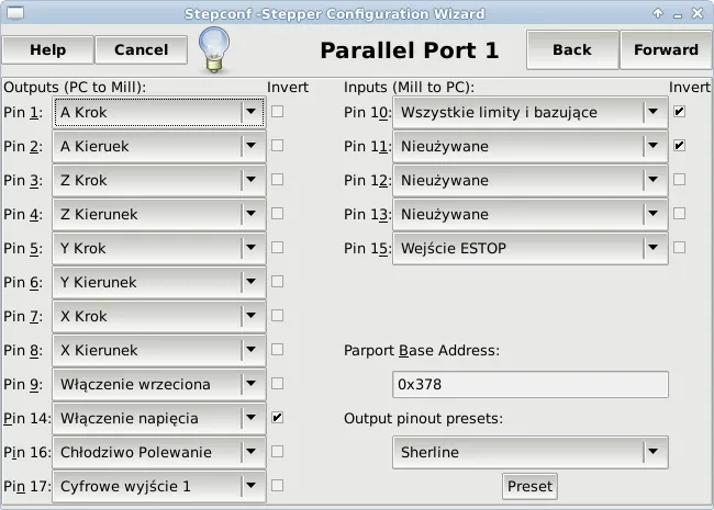
Figure 3b. LPT port settings in LinuxCNC
Why so much isolation? Better safe than sorry! In the first version of the main board, which had no protection, we managed (through our own fault) to damage the LPT port in a freshly bought computer. Before we even bought a second PC, the new main board was already protected on all sides. :)
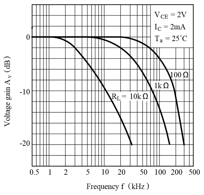
Figure 3c. PC817 frequency characteristics
The PC817 optocoupler isolates all 5 inputs and the ENABLE output (switching on the motor power). It isolates signals that change slowly in time. The datasheet shows that at a collector current of 2 mA, a voltage of 5 V and a load of 100 Ω, the maximum transmitted frequency is typically 80 kHz. For simple buttons, limit switches and the power-on signal, a few Hz is enough, so this optocoupler is fully sufficient. What about the signals driving our stepper motors? We have to look for the information in the datasheet of the driver chip. In the project we use Powerlolu drivers with the Allegro A4989 chip. In the datasheet, the information we need is in the Control Timing section of the table. The shortest duration of the direction signal is 1 μs for both the low and the high state. The minimum period of the STEP signal is 2 μs, i.e. 500 kHz.
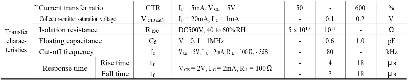
Figure 3d. PC817 optocoupler parameters
That is definitely too much for this isolator. We have to use fast optocouplers, e.g. the 6N137, which according to the documentation transmit signals at up to 10 Mbit/s. For comparison, the maximum speed of our computer’s parallel port is 2 Mbit/s, so that should be enough. Unlike the PC817, this chip unfortunately needs a power supply connection.
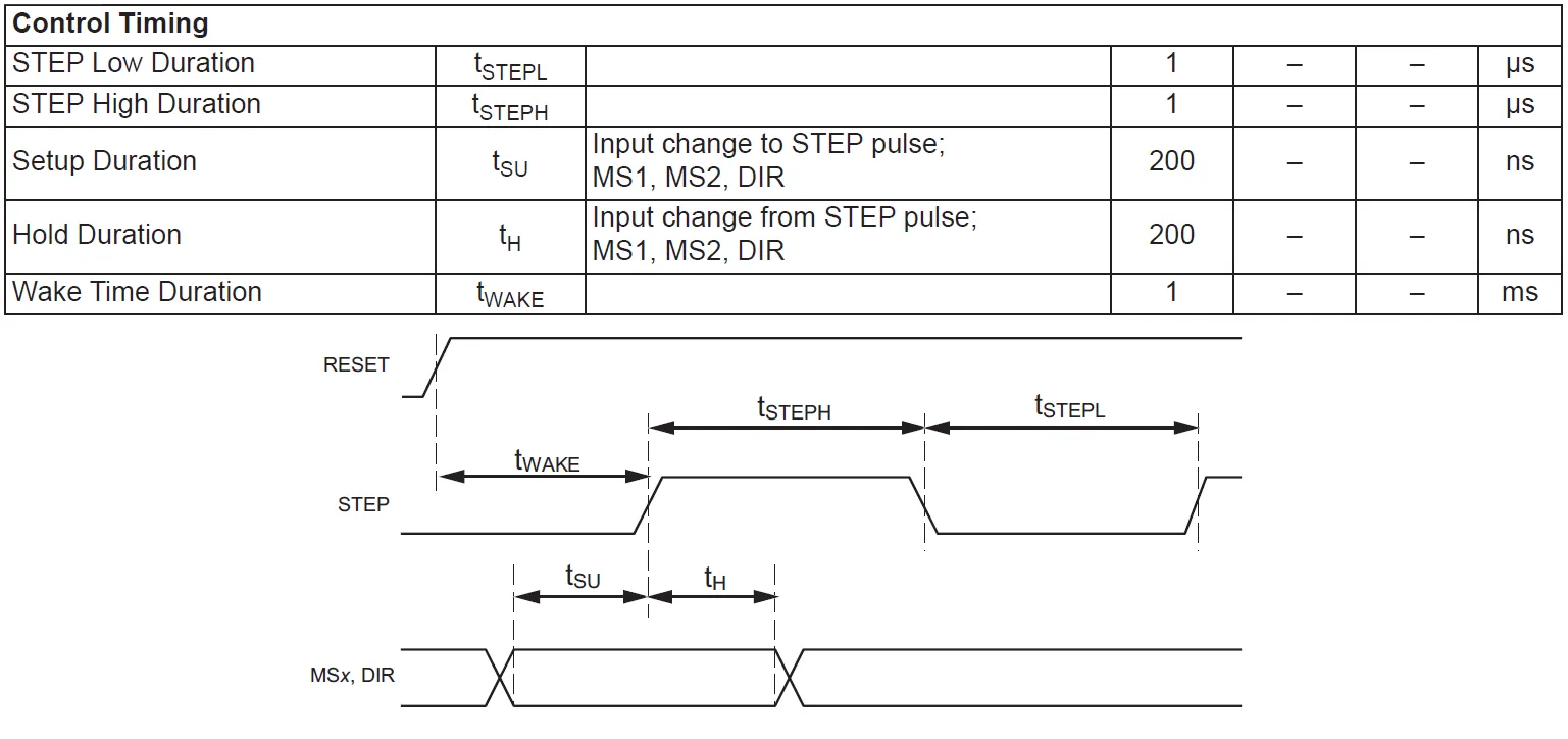
Figure 3e. Switching times of the STEP and DIR signals
To read the isolated STEP and DIRECTION signals reliably we used a 74HC14 Schmitt trigger. The whole schematic of the main board is shown below.
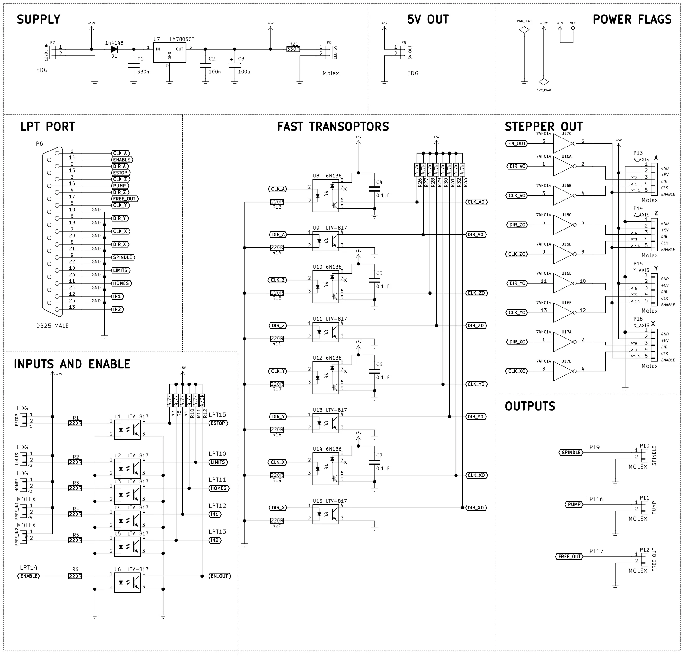
Figure 3f. Electronic schematic of the main board
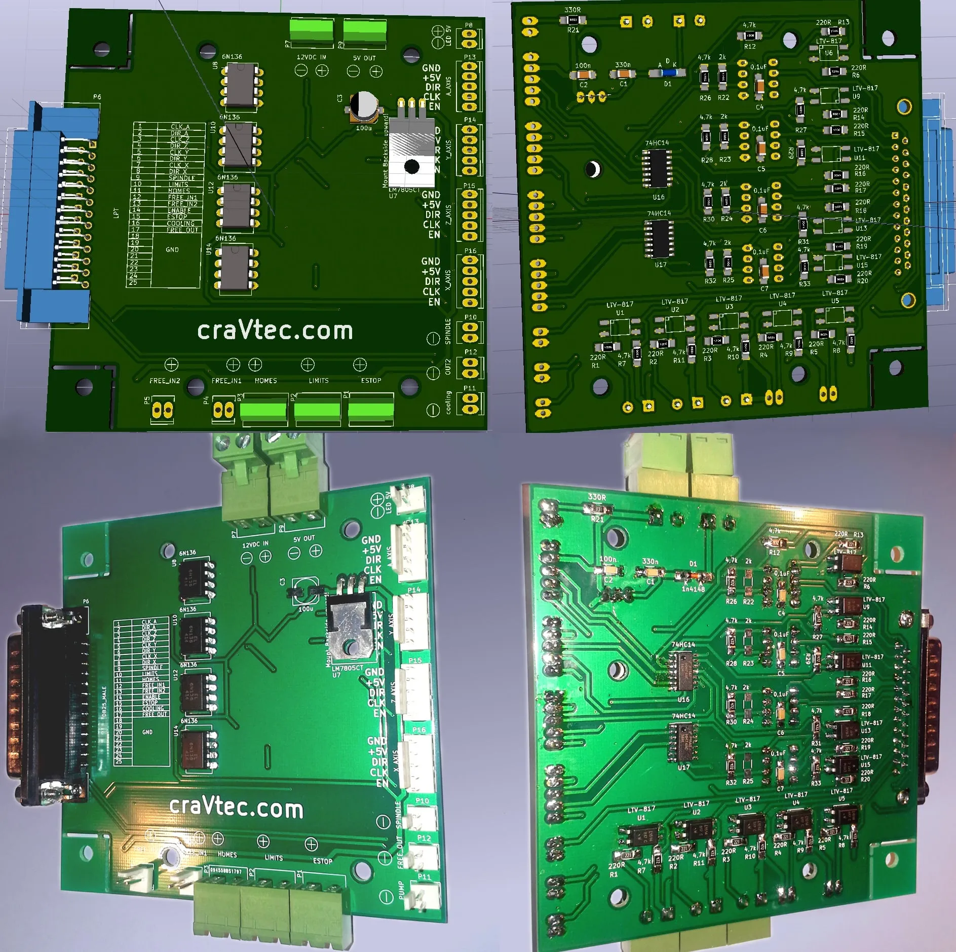
Figure 3g. Our main board: the KiCAD design above, the board made by a Chinese PCB manufacturer below.
4. Stepper motor driver: Powerlolu
This driver is a higher-power replacement for the very popular Pololu driver based on the A4988 chip. Both are available online as open source projects, and the schematics and documentation can be downloaded for free. Pololu drivers can be found on all auction sites and in electronics shops. They are also dirt cheap, so it is practically not worth making them yourself. We recommend ordering them from Fasttech.com, where they cost a little over $2. Powerlolu is a different story: a ready-made one costs less than 50 EUR. The cost can of course be reduced considerably by making it yourself. Our 57h76-3008b stepper motor has a rated current of 4.2 A. There are plenty of different drivers for such power levels on the market, but we decided to test the little-known Powerlolu. Let’s compare the most important parameters of both drivers.
| Parameter | Pololu A4988 | Powerlolu A4989 | Unit |
|---|---|---|---|
| Motor supply voltage | 8-35 | 12-50 | V |
| Logic voltage | 3-5.5 | 3-5.5 | V |
| Maximum motor current | 2 | 10 | A |
| Step division | 1, 1/2, 1/4, 1/8, 1/16 | 1, 1/2, 1/4, 1/16 | - |
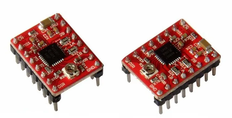
Figure 4a. Pololu drivers
Let’s get to work. From the website http://www.thingiverse.com/thing:40540 we download the schematics and documentation we need, all designed in the free Eagle software. The boards can of course be modified to your own needs. We replaced the jumpers with pin headers, the ARK connectors with wider EDG ones, and the signal socket with a MOLEX. The resistors and the potentiometer for the reference voltage, which we use to set the maximum load current, are chosen by default for a 3.3 V supply. We use 5 V, so we had to change the voltage divider configuration a little. The maximum current also depends on the resistors connected to the SENSE outputs and, of course, on the transistors used (the ones chosen will withstand 17 A with suitable cooling), but we do not change those. Our motor can draw at most 4.2 A, so we have to limit the current. The documentation gives a formula:
ITRIP(MAX)=VREF/(8xRSENSE).
The VREF adjustment range is 0.8 V to 2 V. Substituting the desired 5 A at VREF=2 V, we get:
5=2/(8xRSENSE)
RSENSE=1/20=0.05 OHM
The open source schematic uses two 0.1 ohm resistors in parallel, which gives the required 0.05 ohm. We used the same values. We still have to choose the voltage divider. According to the datasheet, Vref can take values from 0.8 V to 2 V. We chose a 4.3k resistor + a 10k potentiometer and a 22k resistor. The whole schematic is shown in Figure 4b. If we wanted to set the maximum current to 10 A, the formula above tells us we would need two 0.05 OHM resistors in parallel. If the logic is to be powered from a voltage lower than 3.3 V, the resistors will have the values 10k + a 20k potentiometer and a 22k resistor.
The number of motor microsteps is set with jumpers at the MS1 and MS2 pins, as in the table below. Without a jumper the pin has a value of one.
Motor step setting with jumpers:
| MS2 | MS1 | Microstep resolution |
|---|---|---|
| 0 | 0 | Full step |
| 0 | 1 | 1/2 step |
| 1 | 0 | 1/4 step |
| 1 | 1 | 1/16 step |
Jumpers on the PFD1 and PFD2 pins also let us choose the transistor switching (decay) mode. This affects how the current is dissipated, and the settings differ depending on the previously selected step division. In our driver all the jumpers are open, which makes the motor run most smoothly.
The most expensive part of the driver is the chip, which costs over 10 zł at TME (a Polish electronics distributor). You can of course write to Allegro (the chip manufacturer, not to be confused with the Polish auction site) with a student’s request for free samples. We did, and we received 4 A4989 chips and a dozen or so others for driving motors, completely free of charge.
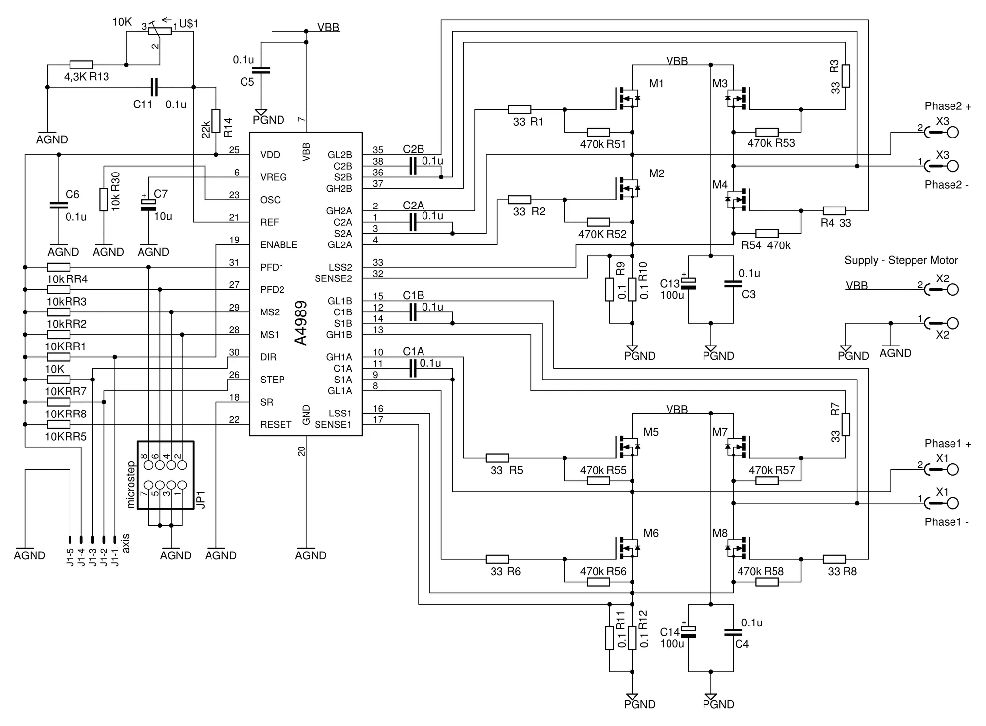
Figure 4b. Electronic schematic of the Powerlolu driver
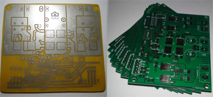
The PCBs can be made yourself or ordered from a manufacturer. Our driver requires a double-sided laminate and a great many vias in very narrow tracks. We made the first two boards ourselves using the toner transfer method. After hours of etching and drilling and days of soldering, we could test the prototypes. They were not made precisely and were not protected, so we had constant problems using them. In addition, a few short circuits (our fault) destroyed the Allegro chips. We decided to have the PCBs made in China, supposedly cheap and of better quality than in Polish factories. We used the offer at http://www.kikipcb.com/. We ordered the boards just before Christmas and they were shipped to Poland after the New Year. The total cost was $22.90 for 10 boards, including one free test board. So let’s calculate: (22.90*3.5)/11 comes to a little over 7 zł per board, of very good quality, with solder mask, tinned pads and finished vias. Conclusion: it is not worth making the boards at home. Add the cost of the components, and the board together with the chip comes to less than 50 zł, not 50 EUR (2014 prices)!!!
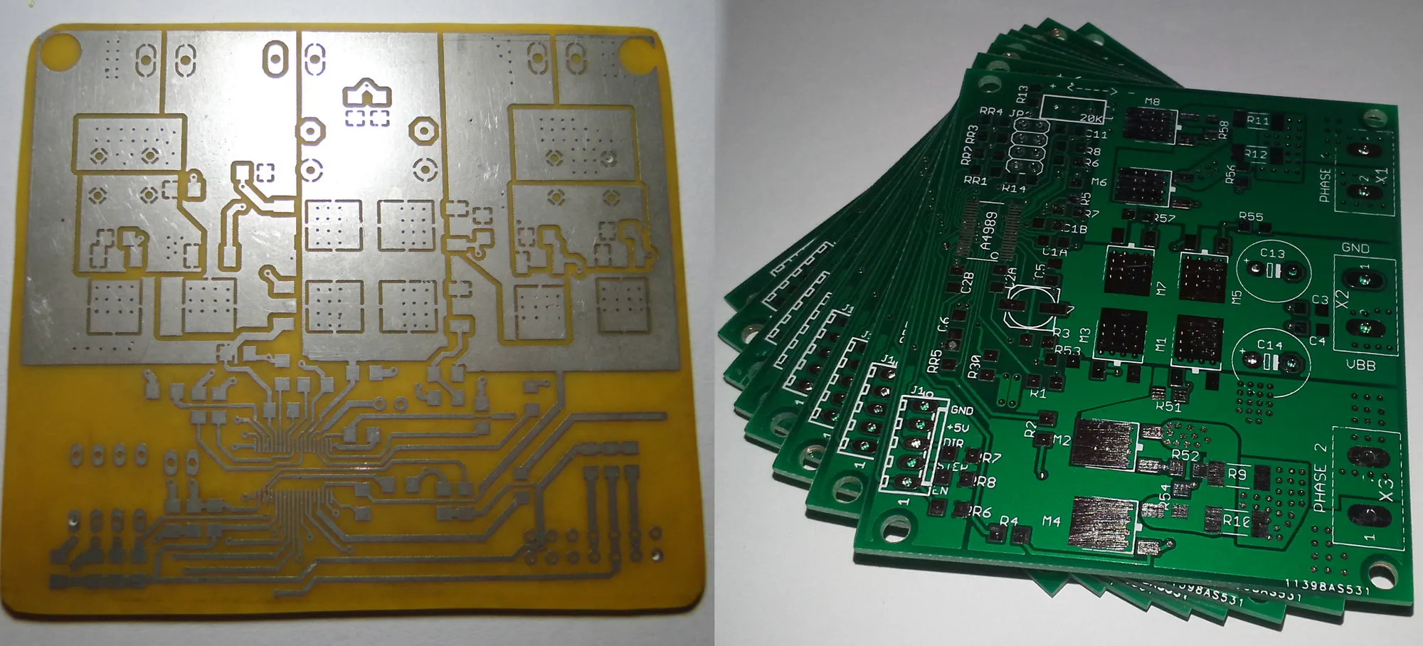
Figure 4c. PCBs: on the left one made at home, on the right one ordered from China
The driver needs 5 signals from the main board. Two of them are the 5 V supply and ground for powering the chip. Besides those:
- ENABLE (EN): the signal that switches on the power
- STEP: the motor step signal
- DIRECTION (DIR): the direction signal, right or left depending on whether it is low or high
On the other side of the board we connect a supply of up to 50 VDC and the appropriate windings of a bipolar motor. Depending on the connection, the lower the inductance and the higher the current, the higher the torque we get. The two phases formed this way are connected to the outermost PHASE inputs, marked 1 and 2. Depending on how the two pairs of wires are connected to them, the motor will turn left or right.
The motor current has to be set using the resistors at Vref and the power resistors (described above).
Stepper motor ratings:
| Connection type | Step angle (deg) | Voltage (V) | Current per phase (A) | Resistance per phase (Ω) | Inductance per phase (mH) | Holding torque (Nm) | Rotor inertia (gcm2) | Weight (kg) |
|---|---|---|---|---|---|---|---|---|
| Unipolar | 1.8 | 2.76 | 3.0 | 0.92 | 2.2 | 1.4 | 480 | 1.0 |
| Bipolar (series) | 1.8 | 3.86 | 2.1 | 1.84 | 8.8 | 2.0 | 480 | 1.0 |
| Bipolar (parallel) | 1.8 | 1.93 | 4.2 | 0.46 | 2.2 | 2.0 | 480 | 1.0 |
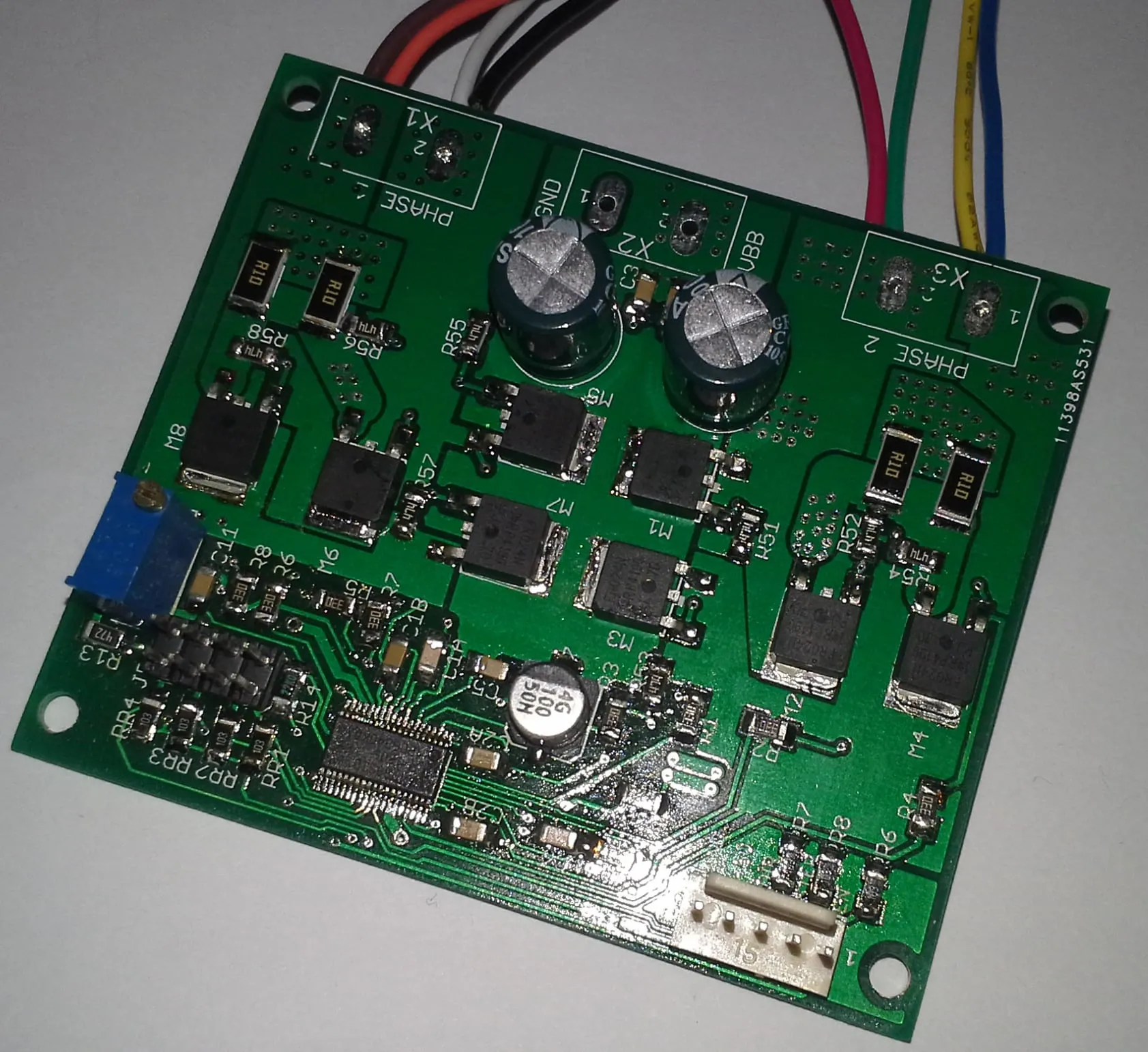
Figure 4d. The Powerlolu PCB soldered by us
Video: the Powerlolu stepper driver in action
5. Output modules
The outputs of the main board are brought out to MOLEX pins. Any module can be connected to an output, for example:
- an optocoupler with a relay for switching DC voltages
- an optotriac and a triac for switching AC voltages
- an optocoupler with a MOSFET transistor for PWM
- a plain indicator LED
- any other output module
We use modules with a triac, which switch on our Kress spindle. The spindle starts automatically as long as the appropriate functions are in our G-code: M03/M04 for clockwise/counterclockwise rotation or M05 to switch the spindle off. We do not have to walk up to the spindle and press the switch by hand. The spindle can also be controlled from the keyboard through LinuxCNC: F9/F10 for clockwise/counterclockwise rotation. You can also connect, for example, a vacuum cleaner for removing chips or a pump with coolant to this module, as long as they do not exceed the triac’s maximum load.
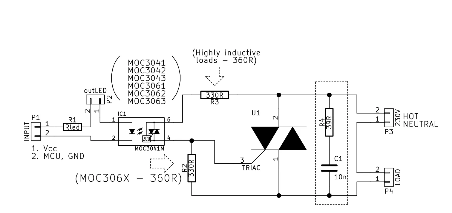
Figure 5a. Schematic of the electronic module with a triac
The output element is driven by 5 V and its current must be limited by a suitable resistor. The elements are connected in series, and we do the calculation for a MOC3041 optotriac and a yellow indicator LED. The MOC3041 documentation gives the voltage drop at a current of 30 mA, which is 1.5 V at most, and the voltage drop across the yellow LED is 2.2 V. We calculate:
5V-1,5V-2,2V=1,3V,
1,3V/0,030A≈43,3Ω.
The nearest resistor value in the E12 series is 47 Ω. There is a place for the limiting resistor in the output module. The LED output can of course be shorted and a correspondingly larger resistor used to limit the triac’s current. The BTA16 triac withstands a continuous load of 16 A of sinusoidal alternating current with a suitably chosen heatsink, which is over 3000 W. The board was designed to fit a Z103 enclosure for DIN rail mounting. The enclosure is available in electronics shops, e.g. TME or Lispol (Polish distributors).
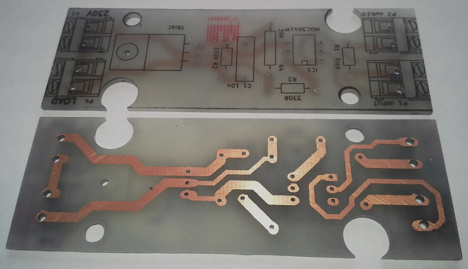
Figure 5b. The output module board. The holes and edges are milled, and the tracks were made using the toner transfer method.
Downloads
| Description | File |
|---|---|
| Documentation in PDF | Documentation.pdf |
| Main board | CNCMainboard.zip |
| Power supply | CNCPowerSupply.zip |
| Modified Powerlolu | Powerlolu.zip |
| Triac output module | CNCTriac.zip |
Info
If anyone is interested, we have a lot of PCBs left over from the manufacturer, as well as soldered drivers and parts. More information in the contact section.