
Feed Drive Calculations for a Trapezoidal Leadscrew
Originally written in Polish and translated into English.
Contents
A feed drive is essential for the proper operation of any machine tool, not only a numerically controlled one. Its job is to move the workpiece (most often linearly) relative to a rotating tool, as in a milling machine, or to move the tool relative to a rotating workpiece, as in a lathe.
In this article I will try to present the basic calculations and some notes on trapezoidal leadscrew drives.
1. Defining the initial conditions
First of all, we have to define the initial conditions, that is, what data we have and what we want to calculate. There are many ways to approach the calculations, but in every case the formulas are the same, just rearranged accordingly.
Let us assume that we have a drive set consisting of a stepper motor and a leadscrew with a nut. The parameters of our set are as follows.
Stepper motor:
- maximum torque M = 1.9 Nm
- maximum rotational speed n = 750 rpm
Screw and nut:
- thread profile Tr 16x4
- steel screw, rolled thread
- brass nut
- friction coefficient between the screw and the nut assumed as µs = 0.12
The torque-speed characteristic of the stepper motor must also be taken into account. For popular motors, such charts are often available from the manufacturer, from the larger topic forums or, as a last resort, you can measure them yourself. I will write a separate article on measuring motor torque in the future. For now, we have to rely on catalogue data available on the Internet.
My calculations use the maximum torque of the motor, although nothing prevents you from calculating the values of interest for the whole torque range.
2. Maximum possible force
To make the dimensions easier to understand, Figure 1 shows each of the diameters.
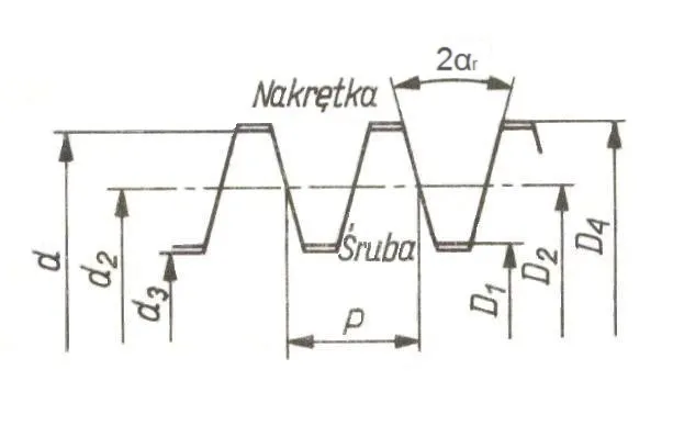
Figure 1. Dimensions of a symmetric trapezoidal thread
The parameters of the selected Tr 16x4 thread are as follows:
- d – nominal (major) diameter of the thread: 16 mm
- P – pitch of the thread: 4 mm
- d3 – minor diameter of the screw: 11.5 mm
- d2 = D2 – pitch diameter (mean contact diameter)
- D1 – minor diameter of the nut: 12 mm
- D4 – major diameter of the nut thread: 16.5 mm
First we need to calculate the basic parameters. The first is the pitch diameter, the mean contact diameter of the screw and nut:
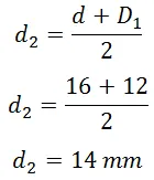
The next parameter is the helix angle of the thread, denoted by γ (gamma).
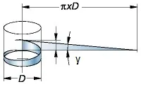
The easiest way to calculate it is to use the tangent function:
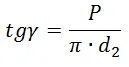
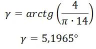
therefore,
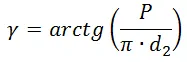
The value of γ can be calculated on almost any scientific calculator or with a spreadsheet function. Remember, however, that Microsoft Excel may calculate the angle and display it in radians.
Since a screw drive is not ideal, we have to take into account the friction force between the mating parts. Note that there are two types of friction: static and kinetic. To bring the calculations closer to reality, I assumed the higher coefficient, the static one. Under favourable conditions and with good lubrication, the friction coefficient between steel and brass can be as low as µs = 0.1. For the calculations I used µs = 0.12. Thus:
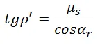
where:
- ρ’ – apparent friction angle
- µs – friction coefficient between the parts
- αr – thread flank angle: αr = 15° for a trapezoidal thread, αr = 30° for a metric thread
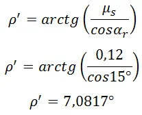
A small note. Let us go back to Figure 1, which shows the basic dimensions of a trapezoidal thread. To simplify dimensioning, the angle 2αr is usually given, which is why αr is 15° for a symmetric trapezoidal thread.
At this point I must mention a very important matter. Threaded joints have a property called SELF-LOCKING. It means that the screw cannot be driven by pushing the nut. In a machine tool, this would mean that an axis module cannot be moved by hand when the drive is switched off. Thanks to self-locking, almost every tightened nut, from a mixer to a car, does not come loose under axial loads.
The self-locking condition is very simple and specific:
If the apparent friction angle (ρ’) is greater than or equal to
the helix angle (γ), the joint
is self-locking.
In addition, these parameters make it possible to calculate the theoretical efficiency of the drive, but more on that later.
The maximum axial force Fs can therefore be calculated from the following relationship:
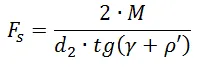
Remember to convert the torque from Nm to Nmm by multiplying by 1000. Otherwise, the pitch diameter ds has to be converted to metres.
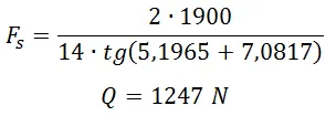
The calculated value already gives some idea of the performance of the chosen drive. Converting the force from newtons to kilograms gives exactly 127 kg. This means that a properly built drive will be able to hold a Z-axis module weighing up to 127 kg. One more correction is needed, because the calculated force applies to the maximum torque generated by the motor. To analyse the generated force accurately, you therefore have to follow the motor’s torque-speed curve.
3. First example
Let us assume the following scenario.
You are building a machine in which the Z-axis module has a mass of m = 100 kg. According to the calculations above, such a drive should cope and the whole machine should work properly. Nothing could be further from the truth. Simple calculations show that the drive will have only a small force reserve for moving the module upwards.
I deliberately skip the calculations and analysis for downward movements, because the load on the drive is then clearly lower.
Our drive has a maximum force of 1247 N, while the Z-axis module weighs 981 N. The force reserve is therefore 266 N. Only thanks to this reserve will the Z-axis module be able to move upwards, or more precisely, accelerate enough to overcome gravity.
Let us go through the formulas to make this clear:
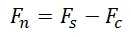
where:
- Fn – driving force
- Fs – force generated by the motor
- Fc – weight of the lifted module
As is easy to see, if the force Fs is less than or equal to Fc, the designed drive is insufficient to move the module.
From the simple formula for force, let us calculate the acceleration of the assumed module:
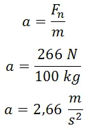
For a full analysis of the drive we need one more value, namely the assumed maximum rapid traverse speed. As a reminder, the selected motor reaches at most 750 rpm, and combined with a screw of 4 mm lead it gives a maximum module speed of 3 m/min. Converted to m/s, this gives f = 0.05 m/s.
We can now calculate the time needed to accelerate the module to the assumed speed:
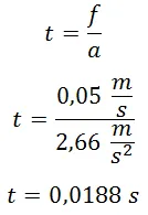
Knowing the acceleration time, we can easily calculate the distance covered during acceleration:
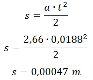
The result above is in metres. Converted to millimetres it gives 0.47 mm. This is an acceptable value, especially for such a feeble drive compared with the loads placed on it. In practice, however, it would make no sense to fit such a weak drive to such a heavy machine. Add to that the fact that the Z module very often has to change direction suddenly, which generates additional forces. If the drive has no power reserve and the parameters set in the control software are close to their upper limits, there is a risk of losing steps (with a stepper motor).
4. Theoretical efficiency of the threaded joint
I also mentioned the efficiency of the screw drive. It is closely related to two parameters. One is the helix angle γ, the other is the apparent friction angle ρ’. For the assumed thread, the two angles are:
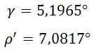
The thread is self-locking because γ < ρ’, so from the start we should expect an efficiency below 50%. Let us proceed with the calculations. The formula for the theoretical efficiency of a threaded joint is as follows:
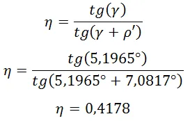
How should this result be understood? Exactly like this: (theoretically) 41.78% of the motor power is transferred to the moving module, and the rest is spent on overcoming motion resistance and generating heat.
Let us let our imagination run and modify the drive a little. Suppose we use a plastic nut, namely PTFE (polytetrafluoroethylene), popularly called Teflon, whose friction coefficient against steel can be as low as µ = 0.04. What would the efficiency of such a system be?
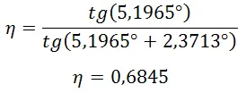
As you can see, we managed to exceed the 50% efficiency threshold, which means the joint is no longer self-locking. The efficiency gain is over 60% compared with a typical steel screw and brass nut. Continuing the analysis, the force available at the drive output rises to Fs = 2043 N. Thanks to this, in the system from example 1 the risk of losing steps is greatly reduced, and the whole drive will work more dynamically.
Still, every rose has its thorns. The mechanical strength of PTFE is far below that of brass, so this solution is recommended mainly for lightly loaded drives.
5. Selecting a screw drive for a machine tool
Let us start with the initial assumptions, which make the further calculations possible.
- maximum feed rate f = 6 [m/min]
- acceleration distance to maximum speed s = 0.1 [mm]
- minimum positioning accuracy of the drive r = 0.02 [mm]
- microstepping division in the driver u = 16 [-]
- number of steps per motor shaft revolution k = 200 [-]
- mass of the moving module m = 20 [kg]
- maximum used motor power (torque) w = 75 [%]
- friction coefficient between the screw and the nut µs = 0.12
As you can see, not all of the motor parameters appear in the assumptions, only the number of basic steps per revolution. I assumed 200 because it is the most common number of steps in motors. With these assumptions we can calculate the drive parameters we are interested in. I also made a simplification by ignoring the rotor inertia and applying a safety margin instead: 75% use of the motor torque.
First, let us calculate the maximum lead of the screw (without any additional gearing) using the data:
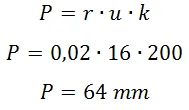
Of course, a screw with such a lead would be very hard to find, not to mention its size. For the further calculations, let us therefore assume a pitch of P = 8 mm. A screw with such a lead can be bought without major problems.
Let us now calculate the output accuracy with the newly selected pitch:
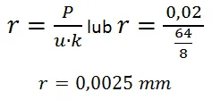
Looking at the trapezoidal screws on sale with a pitch of P = 8 mm, the smallest thread is Tr 22x8. Its diameters are as follows:
- d – 22 mm
- P – 8 mm
- d3 – 14 mm
- D1 – 15 mm
- D4 – 23 mm
- d2 = D2 – 18 mm
With the thread lead selected and the maximum rapid traverse speed known, let us determine the motor speed without gearing:
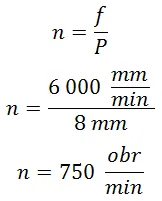
As long as the maximum pulse frequency generated by the computer (see jitter) allows such a motor speed, no additional speed-increasing gearing is needed. We assume we will not install any, but it is no mistake to introduce it as a new variable with a default value of 1:
- speed-increasing gear ratio i = 1 [-]
The next step is to determine the motor torque required to meet the assumed criteria. Before we get to the final formula, we need to calculate the helix angle γ and the apparent friction angle ρ’.
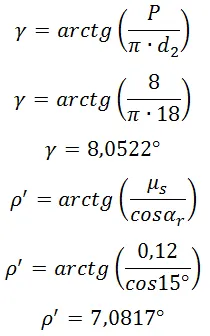
For these parameters, the threaded joint is not self-locking. We can expect an efficiency above 50%. The next stage of the calculations is the analysis of accelerations and forces.
Let us calculate the weight of the moving module:
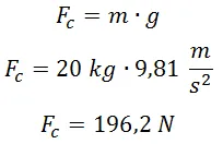
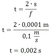
Next, we have to calculate the acceleration the module must undergo to reach the required speed f. Let us start with the acceleration time:
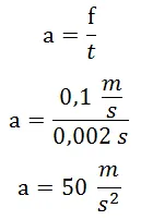
Then the acceleration:
The driving force needed to accelerate such a mass is:
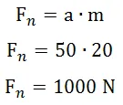
The required axial force on the leadscrew is calculated as follows:
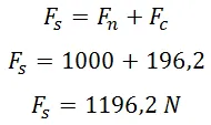
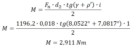
Finally, we can move on to the required motor torque. It is calculated from the following formula:
Bearing in mind that we plan to use 75% of the motor torque, the final minimum motor torque is as follows:
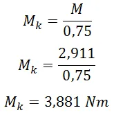
So, for such a drive to move our module, it must provide a torque of at least 2.91 Nm. For safety we added 25% more power to make sure the motor can handle the task. In addition, we used a 1:1 ratio between the motor shaft and the screw, which means the motor shaft can be coupled directly to the screw, or a gear drive with the same number of teeth on both axes can be used.
If a gear drive is used, whether reducing or speed-increasing, remember to change the required motor speed:
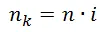
where:
- nk – motor speed [rpm]
- n – screw speed [rpm]
- i – gear ratio [-]
Finally, we can calculate the theoretical efficiency of the drive:
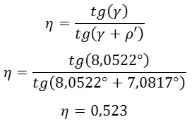
As expected, the efficiency exceeded 50%, so the screw can be driven by moving the nut (the module). Keep this firmly in mind, because if power to the drive motor is lost, the module may slide down on its own, given the low resistance to motion of the switched-off motor. It is worth fitting a component that acts as an automatic brake for this axis, or a counterweight that balances the module with a defined force.
To sum up, correct selection of a feed drive based on a trapezoidal thread is a key factor in the proper operation of a machine tool. It is worth doing at least the basic calculations, to check that the motor is not underpowered and that the acceleration parameters set in the control software do not exceed the limits.