
Mechanical Aspects of a DIY CNC Router: Frame, Guides, Drives
Originally written in Polish and translated into English.
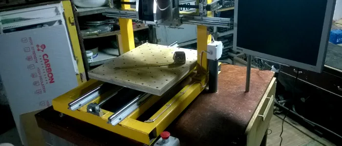
A milling machine, a cutting plotter, a lathe, a drill press… These are just some of the machines you can find in a well-equipped workshop. They all share one feature: they need a stable and strong frame, the structure to which all the modules of the machine are attached. Add various components and drives, and only then can we talk about a functional machine.
In this short article I will try to describe my observations, remarks, curiosities and solutions related to the mechanical part of a milling router.
1. Basic criteria
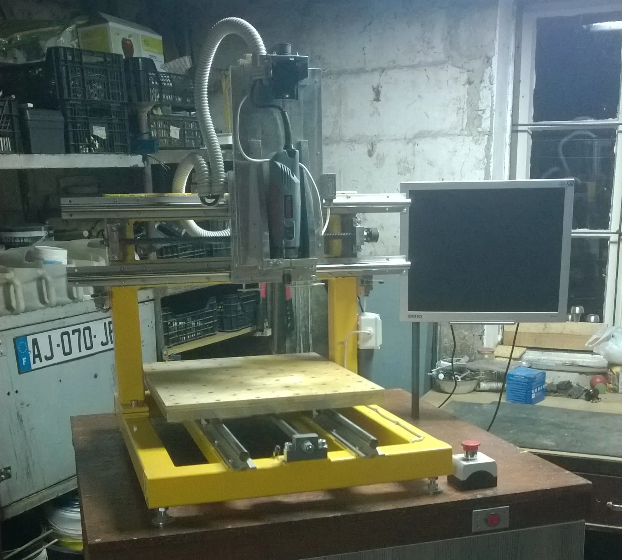
This is where I started any planning of the machine. There is no need to get carried away with components that eat up half the budget right at the start; it is better to choose reasonable, optimal solutions.
Speaking of budget, it is worth setting an initial amount for the project’s expenses. In my case I started with two thousand Polish zlotys. As it turned out, the budget grew gradually, but most importantly, I was able to cover all the costs as I went.
With the funds sorted out, I defined the size of the machine and its capabilities, and checked which components I could make myself and which would have to be bought ready-made. Price was the main factor. I will comment as I go on what I had to make myself (or have made) and what I bought.
As a (then future) engineer, I started with a design in CAD software, to anticipate difficulties, pitfalls and simple details such as cable routing or the position of the homing limit switches.
2. Type of construction
There are plenty of machine designs to be found on the Internet and in technical magazines, so I had to focus on one of the most important aspects: rigidity. With a rather limited budget, I could not afford to experiment. I had to go for a simple construction.
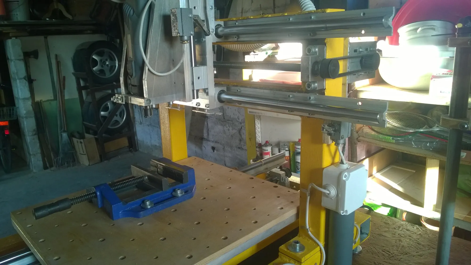
So I chose one that does not require advanced workshop facilities to build, will not swallow half the budget up front, and at the same time offers satisfactory rigidity. I went with a fixed gantry and a moving work table in one axis. The other two linear travels are realised on the gantry and on the module attached to it.
Working area
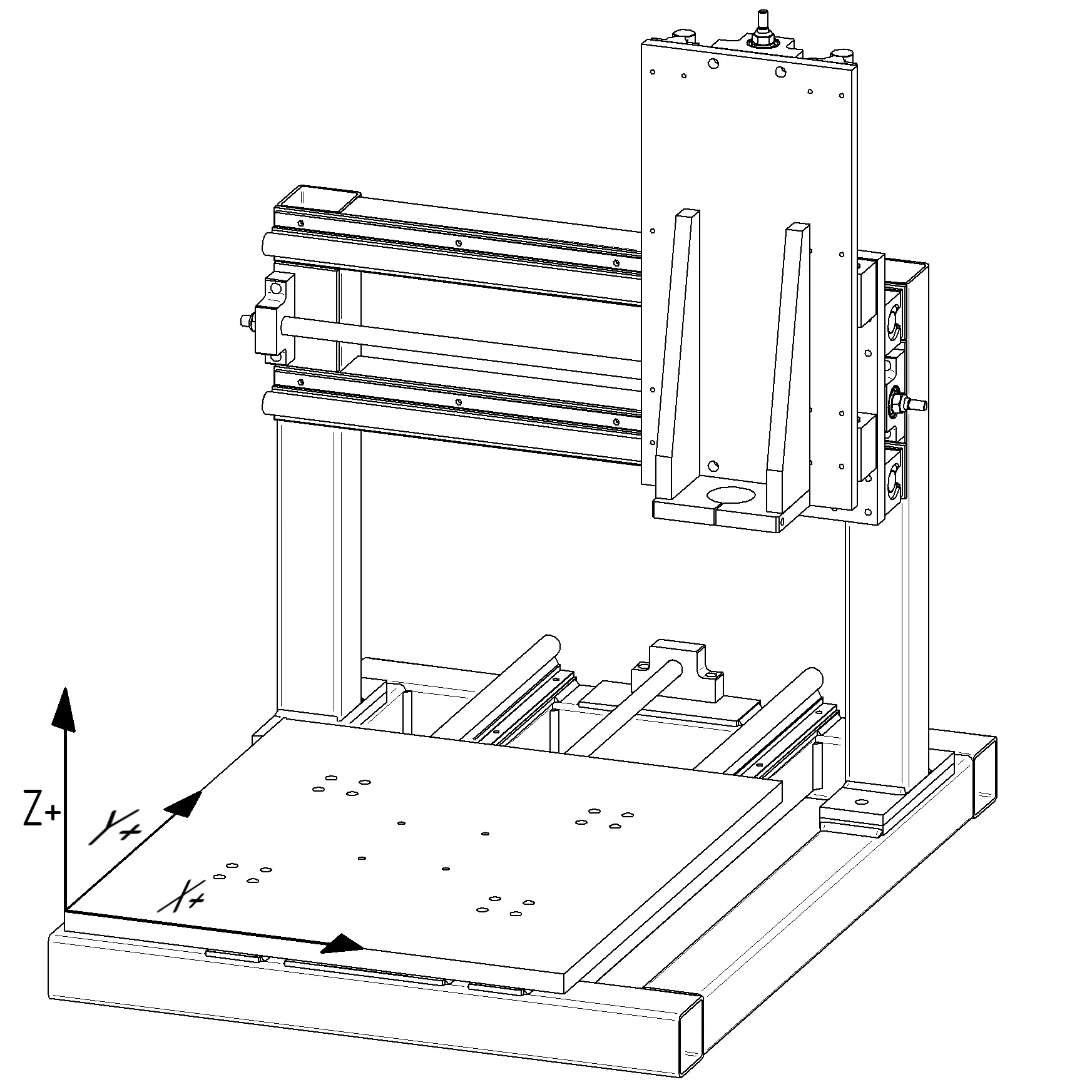
With the construction chosen, I could analyse how large a working area I could squeeze out of it. I also chose a reasonable travel in the vertical axis, so that the whole thing would be of practical use.
In the end, the CAD project produced a machine with the following working travels:
- X axis: 460 mm
- Y axis: 500 mm
- Z axis: 200 mm
3. Materials
The topic of materials should have been covered even before choosing the construction, but I decided to put it here. The reason is simple: the main and auxiliary frames are not the only elements that determine the choice of materials. In my case there are a number of parts made mainly of aluminium alloy, as well as plastics.
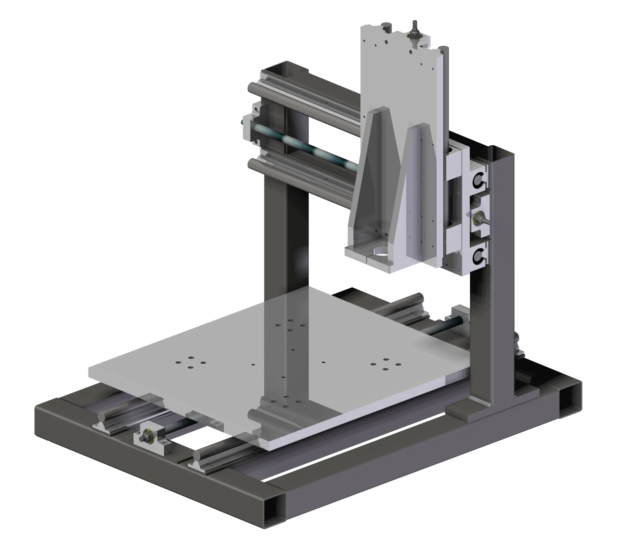
With the first version of the complete machine ready, I only had to check the state of the materials in my workshop, use some of them and buy the rest. A few design modifications were also unavoidable.
To get to the point: for the main (lower) frame and the gantry I used steel, specifically S235JR structural alloy steel, one of the more popular grades. It is easy to weld, friendly to machine and, above all, cheap. In my case it cost about as much as driving a few kilometres to a friend (greetings, Mariusz). The whole structure took a few metres of 60x60x3 profile and a little less of 60x50x3. Among the steel parts I also used flat bars 50 and 60 mm wide. The former, 5 mm thick, were welded on and prepared for machining to take the guide rails, while the latter, 60x10, served as feet fixing the gantry to the main frame.
For all the components to have their place, I needed additional parts. Unfortunately, they had to be made to order. All of them were made from aluminium blanks of various thicknesses and sizes. The alloy I used is EN-AW2017A, known under the Polish Standard (PN) as PA6. It is a grade of aluminium that is much easier to buy than the stronger 7075 (PA9), but it should not be “relegated to the bench”. It is still a solid, strong structural material that is a pleasure to machine.
4. Guide units
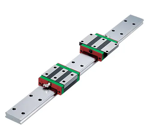
A guide unit, put simply, is an assembly of at least two cooperating elements: a slider (carriage, bushing, etc.) and a guide (linear rail, round shaft, etc.).
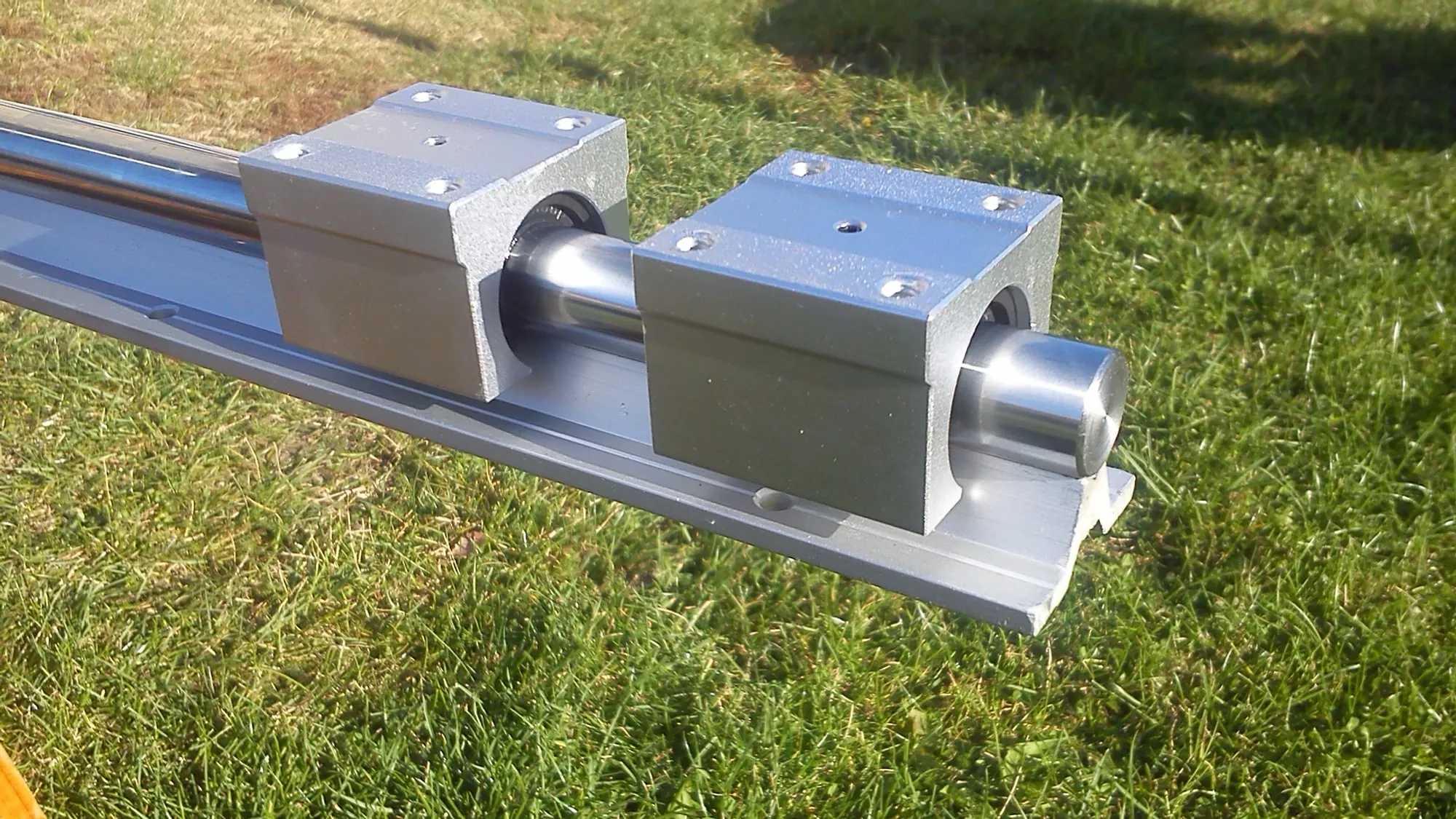
Here too the budget spoke first, so I had to put all linear rails on the wish list, and what went into the basket were fully supported shafts and open linear bearings in housings designed for them.
5. Main drive
What is the main drive? It is the drive that sets the cutting tool in rotary motion. Many people call it a “spindle”, an “axial grinder” or a “milling machine”. While the first two make some sense, the third is not really apt.
In my project I used a Kress spindle, model FME-1 1050. It is a popular model, though loud, and for hobby and academic use it is absolutely fine. The digit “1” in FME means that the speed range has been reduced from the 10k-30k rpm of the standard model to 5k-25k rpm. Speed is (unfortunately) controlled by an electronic circuit that includes a so-called soft-start module and a speed-holding controller.
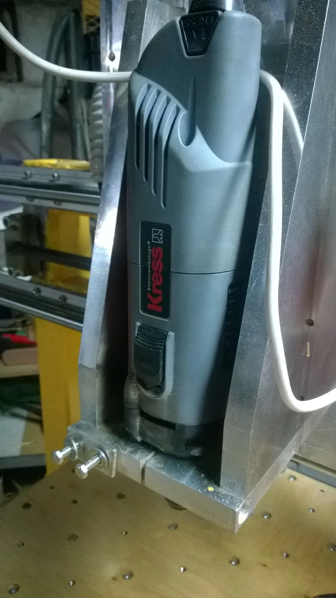
By “unfortunately” I mean that this is not mechanical speed control. With the Kress spindle, limiting the speed also limits the output power, and therefore the torque delivered to the tool.
With mechanical speed control, the motor always runs at its nominal speed and its power is passed to the individual gear stages. The nicest part comes when, by reducing the rotational speed n times, we also increase the torque n times.
6. Feed drive
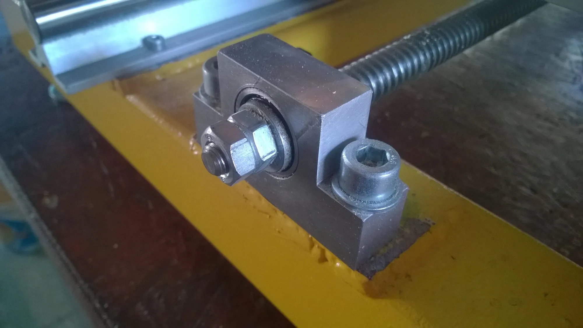
The feed drive is needed to make any movement (translation and/or rotation) of the tool in the working area possible. Seeing how much of the budget the components above had swallowed, I had to settle for a primitive solution: a screw drive with a trapezoidal thread.
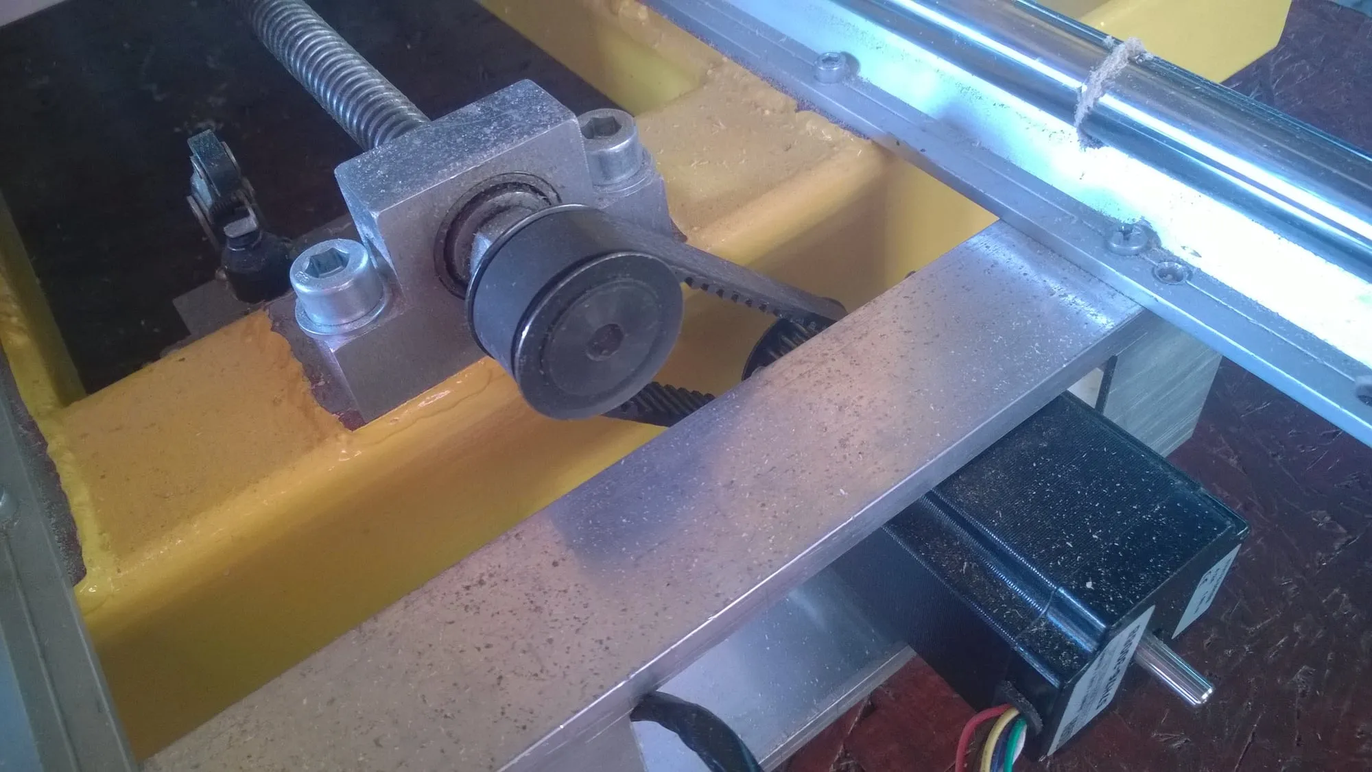
Having experience with this type of drive, the second time around I would think at least three times before going down this road. One thing is certain: the whole drive for three linear axes cost me a little over 200 zlotys, including Tr 16x4 lead screw (2.5 m in total), 6 angular contact ball bearings and 3 bronze nuts. That is a rather laughable price, because even for 250 zlotys it is hard to find a ball screw and nut set, and for a single axis only 300 mm long at that!
7. Summary
The choice of machine construction, materials and exact kinematics is just as important as the electronics that control it. One could say that one depends on the other, and in the end that is how it is. Fortunately, the multitude of ready-made solutions, components and structural elements means that designing, prototyping and building the final machine is not as difficult as it might seem. In addition, as the saying goes, “practice makes perfect”: this project gave me a whole lot of experience in design and later assembly, so that I can apply all the optimal solutions on the next machine.